Clothes dryer

Active Publication Date: 2012-02-09
LG ELECTRONICS INC
View PDF4 Cites 43 Cited by
  • Summary
  • Abstract
  • Description
  • Claims
  • Application Information

AI Technical Summary

Benefits of technology

[0015]Therefore, an object of the present invention is to provide a clothes dryer having a heat pump for shortening drying time and preventing waste of energy, the clothes dryer capable of redu

Problems solved by technology

However, the exhaustion type clothes dryer has a disadvantage such as a large amount of energy consumption, since introduced air is heated only by the heater and then is discharged out.
This may result in a great deal of wasted energy.
However, in this case, the heat exchange means may be overheated due to a limitation of a capacity.
Especially, a compressor used in a heat pump serving as the heat exchange means may be overheated.
In the case that the compressor is o

Method used


Image

  • Clothes dryer
  • Clothes dryer
  • Clothes dryer

Examples


Example

First Embodiment

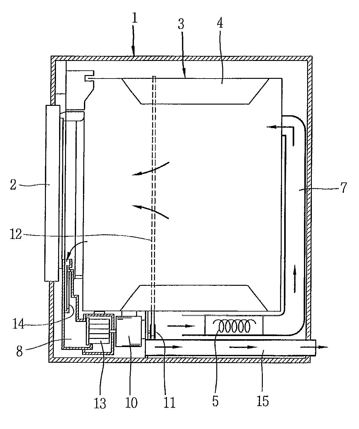
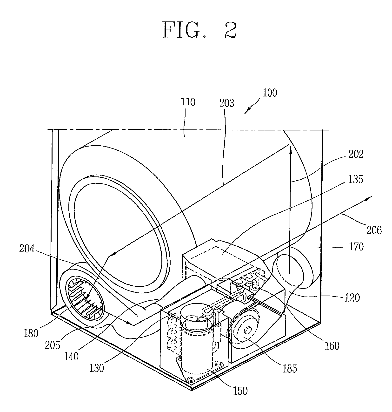
[0067]Referring to FIG. 2, a clothes dryer of the present invention comprises a body 100 which forms the appearance thereof, and a tub 110 rotatably installed in the body 100. The tub 110 is supported so as to be rotatable by supporters (not shown) disposed at front and rear sides.

[0068]At a rear side of the tub, a suction duct 120 is installed in upper and lower side directions of the tub by being extended from a lower portion of the body. The suction duct 120 is installed in the body, and configured to suck external air and to supply the sucked external air into the tub. By the suction duct, formed are suction flow paths 201 and 202 through which air sucked into the tub flows.

[0069]Air sucked through the suction duct 120 is introduced from the outside of the body. More specifically, external air may be introduced into the clothes dryer through an air inlet formed at a bottom surface or a side surface of the body. If air is sucked from the outside of the body, cool ...

Example

Second Embodiment

[0104]Hereinafter, explanations about the same configurations and components of a second embodiment as those of the first embodiment will be omitted.

[0105]Referring to FIG. 12, a clothes dryer of the present invention comprises a body 300 which forms the appearance thereof, and a tub 310 rotatably installed in the body 300. At a rear side of the tub, a suction duct 370 is installed in upper and lower side directions of the tub in the body. The suction duct 370 is configured to suck external air and to supply the sucked external air into the tub. By the suction duct, formed is a suction flow path through which air sucked into the tub flows. Air sucked through the suction duct is introduced from the outside of the body, in a separate manner from air supplied by a circulation duct 320 to be later explained.

[0106]Inside the suction duct 370, installed is a heater 380 for heating sucked air to a high temperature required for a drying operation. The heater 380 rapidly sup...

Example

Third Embodiment

[0138]Hereinafter, explanations about the same configurations and components of a third embodiment as those of the first and second embodiments will be omitted.

[0139]Referring to FIG. 18, a clothes dryer of the third embodiment of the present invention comprises a body 410 which forms the appearance thereof, and a tub 420 rotatably installed in the body 410. The tub 410 is supported so as to be rotatable by supporters (not shown) disposed at front and rear sides.

[0140]At a rear side of the tub, a suction duct 430 is installed in upper and lower side directions of the tub by being extended from a lower portion of the body. The suction duct 430 is installed in the body, and configured to suck external air and to supply the sucked external air into the tub. By the suction duct, formed is a suction flow path through which air sucked into the tub flows.

[0141]A first heat exchanger 440 for heating sucked air is provided at the suction duct 430. Like in the first embodiment...


PUM


Abstract

Disclosed is a clothes dryer having a heat pump, the clothes dryer capable of enhancing energy efficiency by recovering waste heat to the maximum in correspondence to a capacity of the heat pump, capable of enhancing reliability by preventing overheating of a compressor and a heat exchange means, and capable of shortening drying time. The clothes dryer includes a body, a tub rotatably installed in the body, a suction duct installed at the body, and configured to suck external air and to supply the external air into the tub, an exhaustion duct configured to exhaust air having passed through the tub to outside of the body, and a heat pump having a heat exchange means for recovering waste heat by heat-exchanging air passing through the exhaustion duct, wherein part of the air exhausted via the exhaustion duct is heat-exchanged with the heat exchange means of the heat pump.

Description

CROSS-REFERENCE TO RELATED APPLICATION[0001]This application claims the benefit of Korean Patent Application No. 10-2010-0076477, filed on Aug. 9, 2010, Korean Patent Application No. 10-2010-0076481, filed on Aug. 9, 2010, Korean Patent Application No. 10-2010-0076484, filed on Aug. 9, 2010, Korean Patent Application No. 10-2010-0099497, filed on Oct. 12, 2010, Korean Patent Application No. 10-2010-0099499, filed on Oct. 12, 2010 which are hereby incorporated by reference for all purposes as if fully set forth herein.BACKGROUND OF THE INVENTION[0002]1. Field of the Invention[0003]This specification relates to a clothes dryer, and more particularly, to a clothes dryer having a heat pump and heat exchange means, the clothes dryer capable of enhancing energy efficiency by recovering waste heat to the maximum in correspondence to a capacity of the heat pump, capable of enhancing reliability by preventing overheating of a compressor and the heat exchanging means, and capable of shortenin...

Claims


Application Information

Patent Timeline
IPC IPC(8): F26B21/00
CPCD06F58/02D06F58/20D06F58/206Y02B30/52D06F58/28D06F2058/2854D06F2058/2864D06F58/26D06F2103/36D06F2105/24D06F58/34D06F2105/32
Inventor RYOO, BYEONGJOYE, SUNGMINKIM, SEONGHWANAHN, SEUNGPHYOSONG, SUNGHO
Owner LG ELECTRONICS INC
Why Eureka
Try Eureka