Foil removal device and a method for removing a foil from a tire tread

Active Publication Date: 2017-06-08
VMI HOLLAND BV
View PDF17 Cites 10 Cited by
  • Summary
  • Abstract
  • Description
  • Claims
  • Application Information

AI Technical Summary

Benefits of technology

[0028]In an embodiment the tape applicator holds a supply of tape that is substantially longer the length of the tape that is being applied to the foil, wherein the foil removal device is provided with a cutter, wherein the method comprises the step of cutting off the tape from the supply of tape after application to the foil. The tape applicator can thus provide a plurality of lengths of tape, for subsequent cycles of removal. As the tape is cut at a definitive length, the amount of tape used to remove the foil can be kept to a minimum, thereby reducing the amount of waste during the removal.
[0029]In an embodiment the foil collection unit receives the foil at or near the one end thereof that is adjacent to the tape. The combined weight of the foil and the tape can cause the one end of the foil to bend downwards on the opposite side of the winding element with respect to the remaining part of the foil, thereby reducing the chances that the foil releases from the winding element. Furthermore, the combined thickness of the tape and the foil may be greater than the distance between the pins of the winding

Problems solved by technology

The increasing length of the part of the foil that is being removed would be subject to slacking, which could potentially cause the removed part of the foi

Method used


Image

  • Foil removal device and a method for removing a foil from a tire tread
  • Foil removal device and a method for removing a foil from a tire tread
  • Foil removal device and a method for removing a foil from a tire tread

Examples


Embodiment Construction

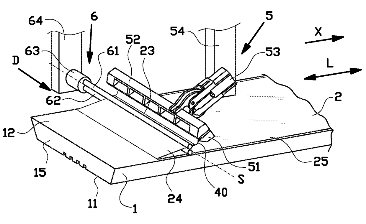
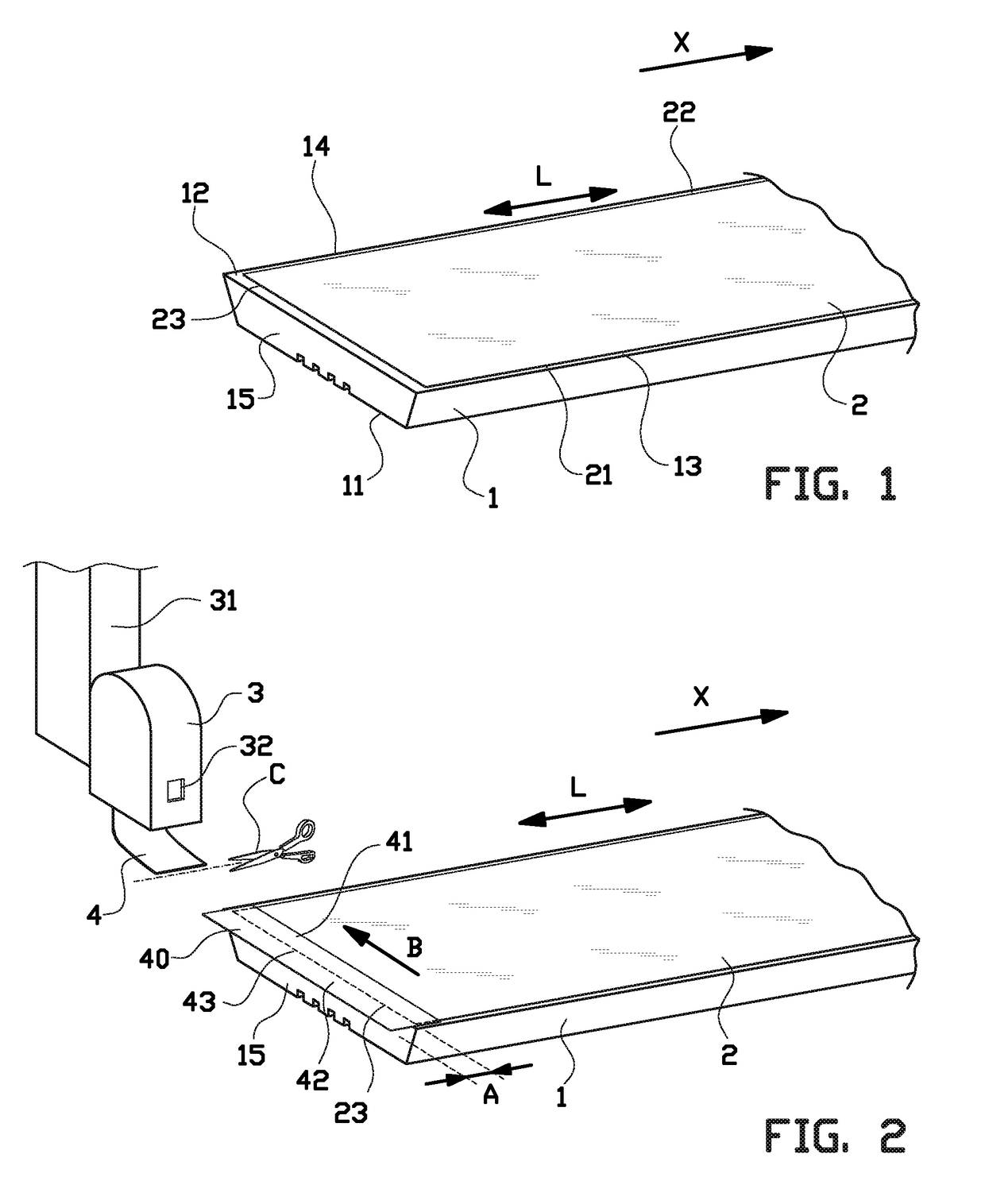
[0038]FIG. 1 shows an elongate tire tread 1 for circumferential application to or retreading of a tire or a tire carcass (not shown). The tire tread 1 comprises an outer surface or running surface 11 which, after application, is facing radially outwards to be in contact with a road. The tire tread 1 further comprises an application side 12 which, after application, faces radially inwards and is applied or attached to the tire carcass. The tire tread 1 is provided with two longitudinal sides 13, 14 defining a longitudinal direction L. The tire tread 1, considered in the longitudinal direction L, has two transverse ends or edges that form the leading end and the trailing end of the tire tread 1 during application. Only one end 15 of the two ends is shown in FIG. 1. It is observed that removal of the protective foil can start at any of the two ends.

[0039]As shown in FIG. 1, a foil, in particular a protective film or protective foil 2 is provided on the application side 12 of the tire t...


PUM

PropertyMeasurementUnit
Angleaaaaaaaaaa
Lengthaaaaaaaaaa
Velocityaaaaaaaaaa

Abstract

Provided is a foil removal device and a method for removing a foil from a tire tread in a removal direction, wherein the foil removal device includes a foil collection unit with a winding element, a winding drive for receiving the foil at or near one of the ends of the foil, a gripper for engaging the foil prior to the removal of the foil and a gripper drive for moving the gripper from the gripping position towards the foil collection unit to partially remove the foil from the tire tread. The gripper is arranged for releasing the foil when the foil collection unit has received the foil. The winding drive is arranged for driving the winding element to engage and subsequently remove the foil. The removal device includes a displacement drive for moving the foil collection unit simultaneously with the winding drive driving the winding element.

Description

BACKGROUND[0001]The invention relates to a foil removal device and a method for removing a protective foil from a tire tread.[0002]Tire treads are usually provided with a protective foil on the application side. This protective foil needs to be removed prior to application of the tire tread to a tire carcass. Currently, the protective foil is manually removed. The removal is a time consuming process which dominates the tire tread application cycle time. Furthermore, the protective foil tears easily and is hard and heavy to be consistently removed by hand. Finally, any manual intervention during or after removal of the protective foil is likely to damage or contaminate the exposed application side of the tire tread.[0003]It is an object of the present invention to provide a foil removal device and a method for removing a protective foil from a tire tread, which at least partially solves one or more of the aforementioned drawbacks of manual removal.SUMMARY OF THE INVENTION[0004]Accord...

Claims


Application Information

Patent Timeline
IPC IPC(8): B65H19/28B65H20/16B65H18/02
CPCB65H19/286B65H18/026B65H2301/41427B65H2301/41306B65H20/16B29D30/08B60C19/00B65H18/10B65H2301/4127B65H2801/93Y10T156/1168Y10T156/1978B32B43/006
Inventor KRAMER, ROEL
Owner VMI HOLLAND BV
Why Eureka
Try Eureka