
Expansion joint cover with modular center

Active Publication Date: 2006-07-25
E M E H
View PDF18 Cites 7 Cited by
  • Summary
  • Abstract
  • Description
  • Claims
  • Application Information

AI Technical Summary

Benefits of technology

[0004]One object of the present invention is to provide a center plate for an expansion joint cover that for any given strength requires significantly less material and that is made from stock that is considerably less costly than aluminum plate. Another object is to reduce the amount of waste resulting from production of center plates. It is also an object to simplify and reduce the costs of the assembly of a center plate to adapters or nosings to form a cover for an expansion joint cover. It is also desired to facilitate the fastening of accessory components to a center plate.
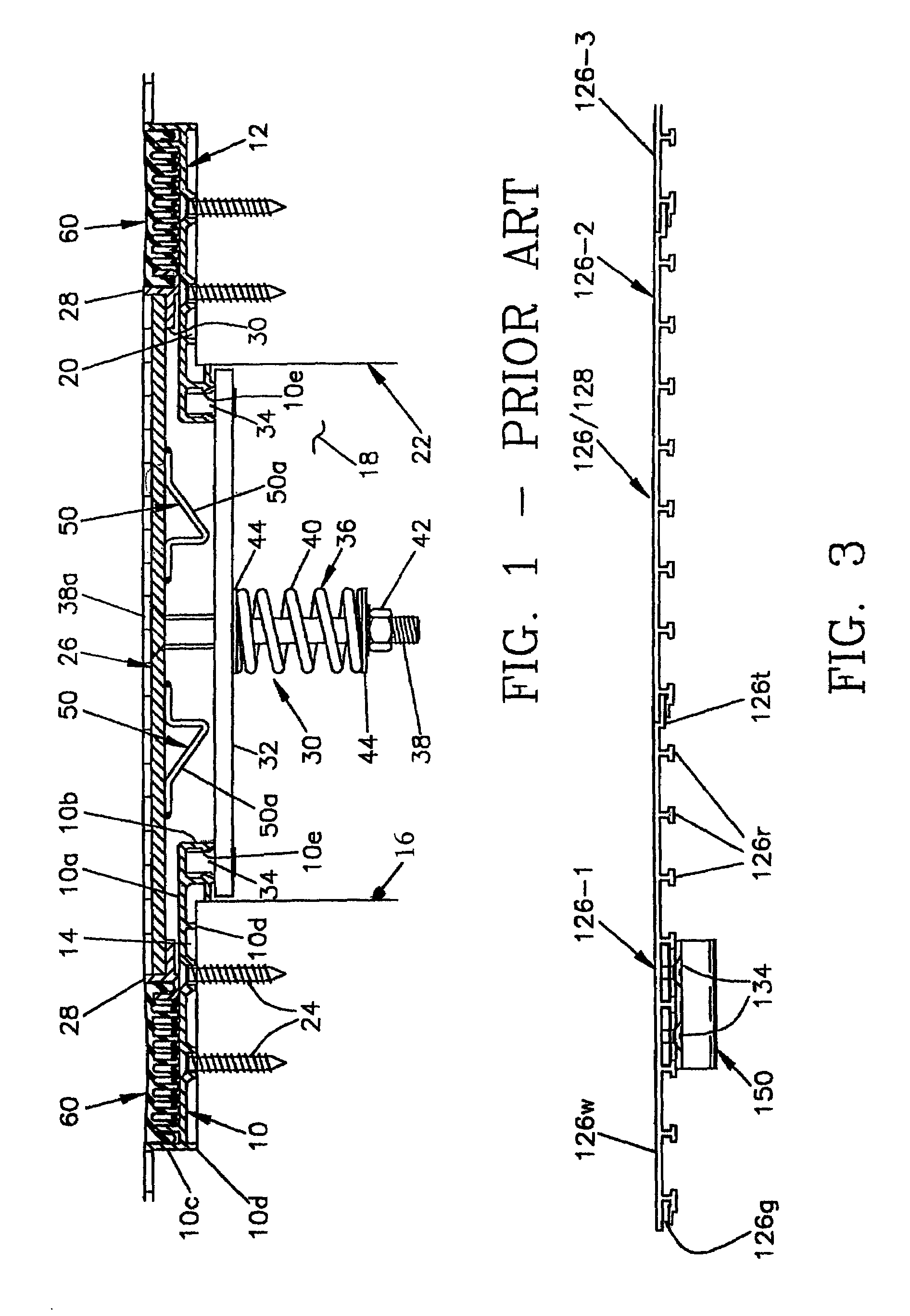
[0010]The cross-sectional shape of the formed members permits the area moment of inertia to be increased significantly, as compared to a plate—hence, for a given bending strength, the controlling property for expansion joint cover center plates, formed members may have a total cross-sectional area, and thus weight, that is about 30% less than the area of a plate;
[0012]The relatively small thickness of the formed members makes it economical to use mechanical fasteners rather than welding for connections to other members; and
[0013]forming by extrusion or roll-forming makes it possible to form cross-sectional shapes, such as flutes or grooves, that enhance bonding of floor surface or subsurface materials to the center plate and permit mechanical attachment of accessories to the center plate.
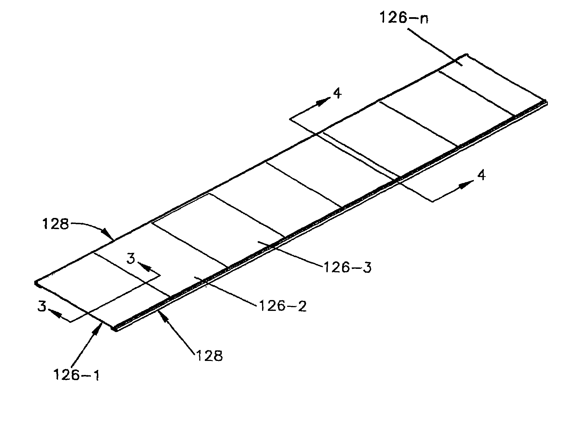
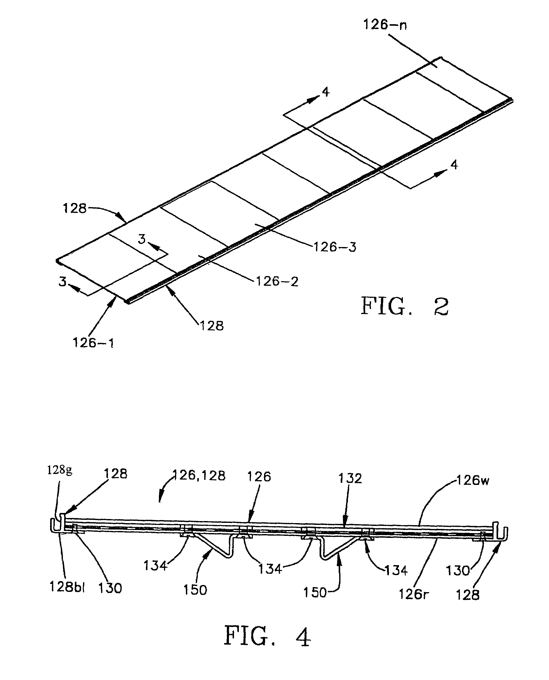
[0016]A common form of center plate for an expansion joint cover provides a flat upper surface on which a finish floor covering, such as vinyl tile or carpet, is supported. For that purpose, one form of modular center plate is made from extruded members, each of which has a continuous planar upper web portion. The bending strength is provided by a plurality of spaced apart dependent ribs extending downwardly from the web portion. An advantageous form for the ribs is an inverted “T”-shape in cross-section, which adds material at the lower extremity farthest from the neutral axis of bending, thus increasing the bending strength. The “T” shaped ribs also can receive nut plates by which accessories, such as deflectors and mounts for centering turn bars, can be fastened to the underside of the center plate.
[0017]Where the center plate is formed to provide a pan or trough for floor finishes such as natural stone, poured pavers, bricks or the like, each of the formed members may be corrugated. In addition to increasing the bending strength, as compared with a plate, corrugations enhance the bonding of a cementitious bed for the floor material or for a concrete floor. Corrugations forming dovetail grooves facing upwardly are desirable for that purpose. In particular, each of the formed members may have a plurality of transversely spaced-apart planar upper web portions, a plurality of transversely spaced-apart planar lower web portions staggered between the upper web portions, and a rib portion joining each edge of each upper web portion to an edge of each lower web portion. That form of corrugations maximizes the amounts of material farthest above and below the neutral axis of bending for high bending strength. Ordinarily, the upper web portions of all of the formed members are coplanar, and the lower web portions of all of the formed members are likewise coplanar.

Problems solved by technology

Aluminum plate stock is relatively costly.
Fabrication of the center plates from plate stock also involves a fair amount of waste.
The cost of a cover for a seismic expansion joint cover can be appreciable, due to the high cost of the plate stock, the waste, and the labor and capital costs for welding the adapters or nosings to the center plate.

Method used


Image

  • Expansion joint cover with modular center
  • Expansion joint cover with modular center
  • Expansion joint cover with modular center

Examples


Embodiment Construction

[0034]U.S. Pat. No. 5,078,529 (Moulton, 1992, hereinafter “the '529 patent”), which is owned by the assignee of the present invention, describes and shows an expansion joint cover in which the exposed surface of a cover is normally—“normally” meaning at all times other than in an earthquake that produces large motions of the building members—held flush with the surfaces of the building members on opposite sides of the expansion gap by resilient hold-down assemblies. The hold-down assemblies include turning bars that maintain the cover centered in the gap. In an earthquake, the hold-down assemblies allow the cover to lift up so that the edges lie above the surfaces of the building members when they move toward each other, thereby preventing the cover from being caught between the building members and being destroyed. Gaskets installed in the gaps between adapters along the edges of the cover and the frames of the expansion joint cover are configured to release in an earthquake. The e...


PUM

PropertyMeasurementUnit
Frictionaaaaaaaaaa
Expansion enthalpyaaaaaaaaaa

Abstract

A modular center plate for a cover that bridges the expansion gap and is supported by frame members of an expansion joint cover is made up of a plurality of formed members, each formed member being rectangular in plan and of uniform cross-section along an axis and having side edges parallel to the axis. The formed members are arranged with their side edges adjacent each other and with their ends overlying the support surfaces of the frame members of the expansion joint cover. End frame members are attached to the end edges of the formed members.

Description

REFERENCE TO PRIOR APPLICATION[0001]The present application is based on U.S. Provisional Patent Application No. 60 / 139,421 filed Jun. 16, 1999.BACKGROUND OF THE INVENTION[0002]In relatively large buildings designed to withstand earthquakes, the expansion joints are virtually always designed to endure excursions of the building members at the joints of more than four inches and may be designed for excursions of up to 20 inches or more. Conventionally, the expansion gap is bridged by an elongated cover, one side of which is supported on a frame affixed to a building member on one side of the gap and the other side of which is supported on a frame affixed to a building member on the other side of the gap. Ordinarily, the cover of an expansion joint cover is fabricated from a flat center plate of aluminum plate stock and an adapter or nosing along each side. The ability of the center plate to support loads is, of course, a function of the thickness of the plate material. The wider the e...

Claims


Application Information

Patent Timeline
IPC IPC(8): E04B1/62E04F15/14E04F15/22
CPCE04F15/14E04B1/681
Inventor SHREINER, THOMAS A.WILLIAMS, HOWARD J.
Owner E M E H
Learn More