Safety valve control system and method of use

a control system and safety valve technology, applied in the direction of water supply installation, survey, borehole/well accessories, etc., can solve the problems of reliance on tubing fluid pressure in the safety valve system, the safety valve cannot be unilaterally operated as desired, and the safety valve system is not new in the field of safety valve control system

Inactive Publication Date: 2012-02-09
SAFOCO
View PDF10 Cites 69 Cited by
  • Summary
  • Abstract
  • Description
  • Claims
  • Application Information

AI Technical Summary

Benefits of technology

[0009]In one embodiment, a safety valve control system for controlling a safety valve may include a remotely operable control assembly and a first transducer in communication with the control assembly. The first transducer may be operable to measure a physical property and communicate a signal to the control assembly corresponding to the measured physical property. A valve assembly and a pump assembly may also be in communication with the control assembly. A fluid reservoir may be in communication with pump assembly, the valve assembly, and the safety valve. The control assembly may be operable to actuate the pump assembly to supply fluid from the fluid reservoir to the safety valve to actuate the safety valve into an open position, and may be operable to actuate the valve assembly to return fluid from the safety valve to the fluid reservoir to actuate the safety valve into a closed position.
[0010]In one embodiment, a method for controlling a

Problems solved by technology

There are numerous drawbacks to the prior art safety valve systems.
One drawback includes the reliance of the safety valves on fluid pressure in the tubing system.
These safety valves cannot be unilaterally operated as desired.
Another drawb

Method used


Image

  • Safety valve control system and method of use
  • Safety valve control system and method of use
  • Safety valve control system and method of use

Examples


Embodiment Construction

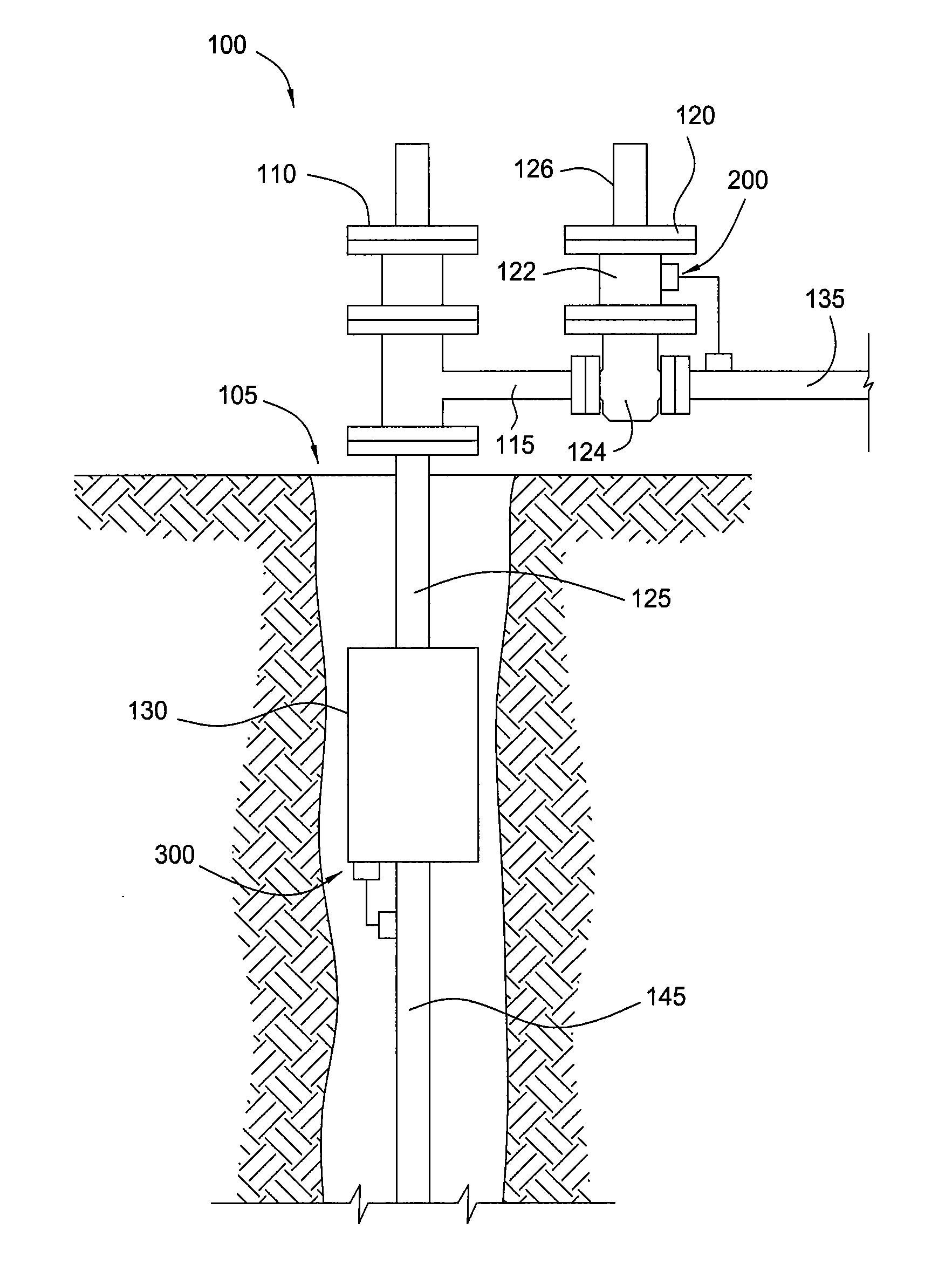
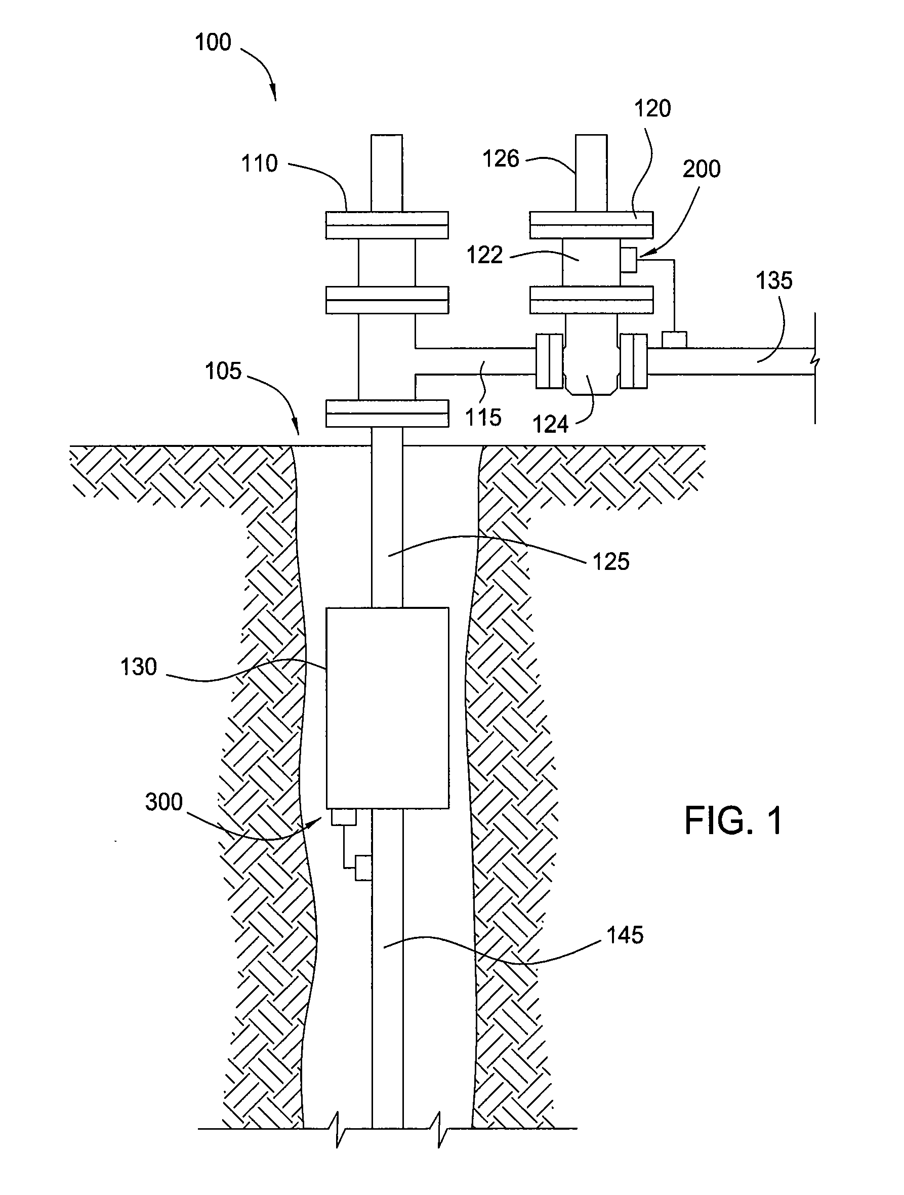
[0023]FIG. 1 illustrates a wellhead control system 100 of an oil / gas well according to one embodiment. The wellhead control system 100 is configured to control the recovery of fluids, such as hydrocarbons, from a reservoir through a primary wellbore 105. The wellhead control system 100 includes a tree 110 having a series of valve and flow control devices, a surface safety valve 120 in communication with the tree 100 via tubing 115, and a subsurface safety valve 130 in communication with the tree 100 via tubing 125. The subsurface safety valve 130 may also be in communication with a well production flow line 145 used to recover oil and / or gas from the oil / gas well. The surface safety valve 120 may also be in communication with a surface production flow line 135 used to direct any recovered fluids to one or more locations downstream of the wellhead control system 100 for further processing and / or storage. In one embodiment, the safety valves 120, 130 may include pneumatically or hydra...


PUM


Abstract

A safety valve control system may include a remotely operable control assembly; a first transducer, a valve assembly, and a pump assembly in communication with the control assembly; and a fluid reservoir in communication with the valve and pump assemblies and a safety valve. The control assembly is operable to actuate the pump and valve assemblies to supply and return fluid from the fluid reservoir to actuate the safety valve into open and closed positions, in response to one or more signals received from the first transducer. A method of operation may include maintaining the safety valve in an open position while sensing a physical property with the control system; communicating a signal corresponding to the sensed physical property to the control system; and automatically closing the safety valve in response to a comparison of the sensed physical property to a pre-set condition.

Description

CROSS REFERENCE TO RELATED APPLICATION[0001]This application claims benefit of co-pending U.S. Provisional Patent Application Ser. No. 61 / 370,721, filed Aug. 4, 2010, and co-pending U.S. Provisional Patent Application Ser. No. 61 / 415,238, filed Nov. 18, 2010, the disclosures of which are herein incorporated by reference in their entirety.BACKGROUND OF THE INVENTION[0002]1. Field of the Invention[0003]Embodiments of the invention relate to a wellhead control system for oil and gas wells. In particular, embodiments of the invention relate to systems and methods of an emergency shut down control system for surface and subsurface safety valves.[0004]2. Description of the Related Art[0005]A wellhead system may be used to control the flow of fluids recovered from an oil and gas well in a safe and efficient manner. The wellhead system may include a variety of flow control devices, such as valves, which are operable direct fluid flow through a tubing system connected to the wellhead system....

Claims


Application Information

Patent Timeline
IPC IPC(8): F16K31/02
CPCE21B47/12F15B20/00F15B2211/31576F15B2211/6303F16K37/0091F15B2211/7052E21B34/02E21B34/10E21B34/16F15B2211/665Y10T137/7761Y10T137/0318F16K17/046E21B34/025
Inventor LYMBEROPOULOS, DAVID
Owner SAFOCO
Why Eureka
Try Eureka