Oil spill recovery vessel

Inactive Publication Date: 2012-02-09
LANCASTER DAVID W
View PDF5 Cites 3 Cited by
  • Summary
  • Abstract
  • Description
  • Claims
  • Application Information

AI Technical Summary

Benefits of technology

[0010]The oil spill recovery vessel has a shallow draft and is configured particularly for oil recovery missions in relatively shallow water, although it may be used in deeper w

Problems solved by technology

While the recovery of such oil and natural gas deposits has served to expand and continue the availability of energy produced by such deposits, this technology is not without its potential problems.
However, when an oil spill occurs at sea, the potential for enviro

Method used


Image

  • Oil spill recovery vessel
  • Oil spill recovery vessel
  • Oil spill recovery vessel

Examples


Embodiment Construction

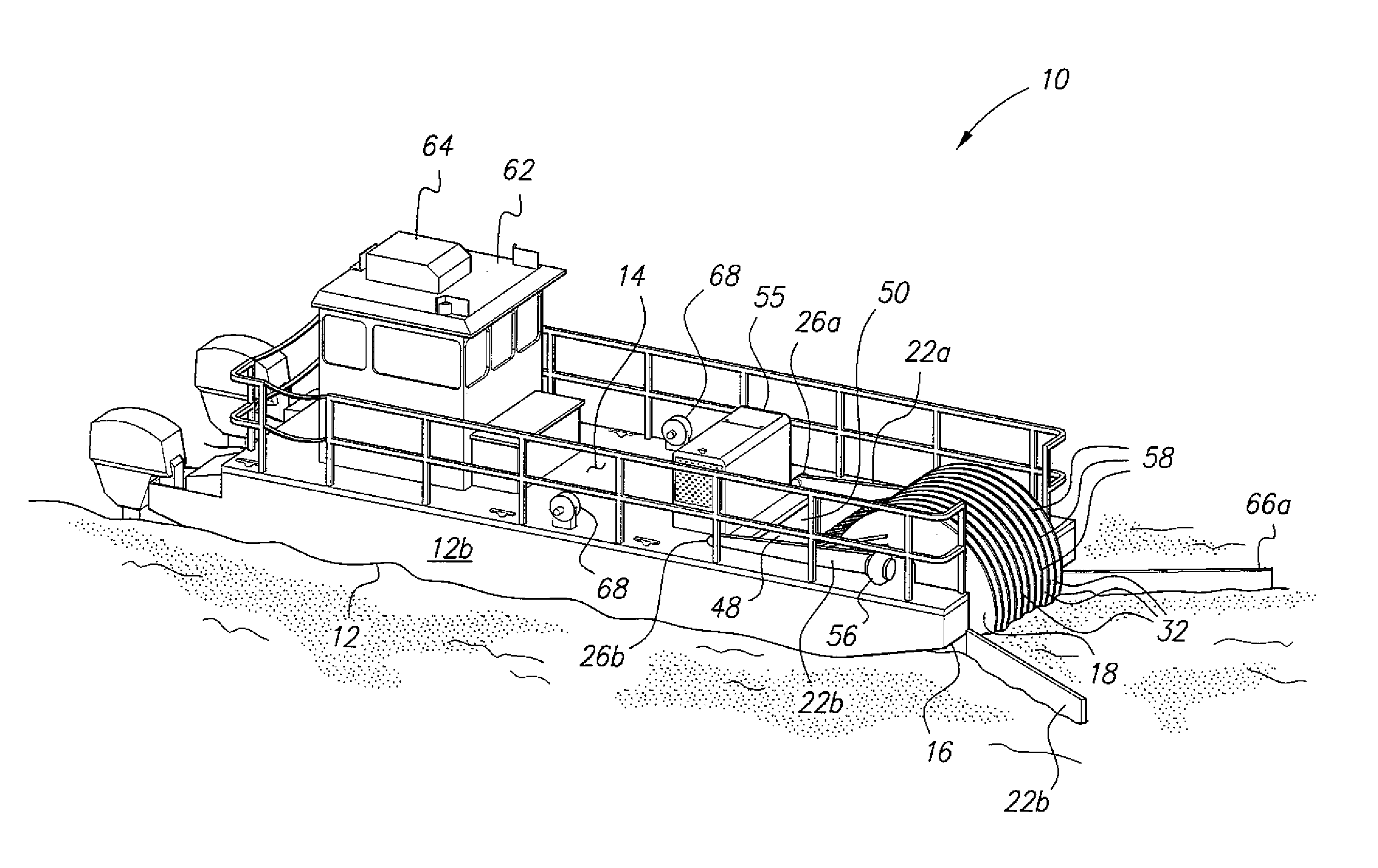
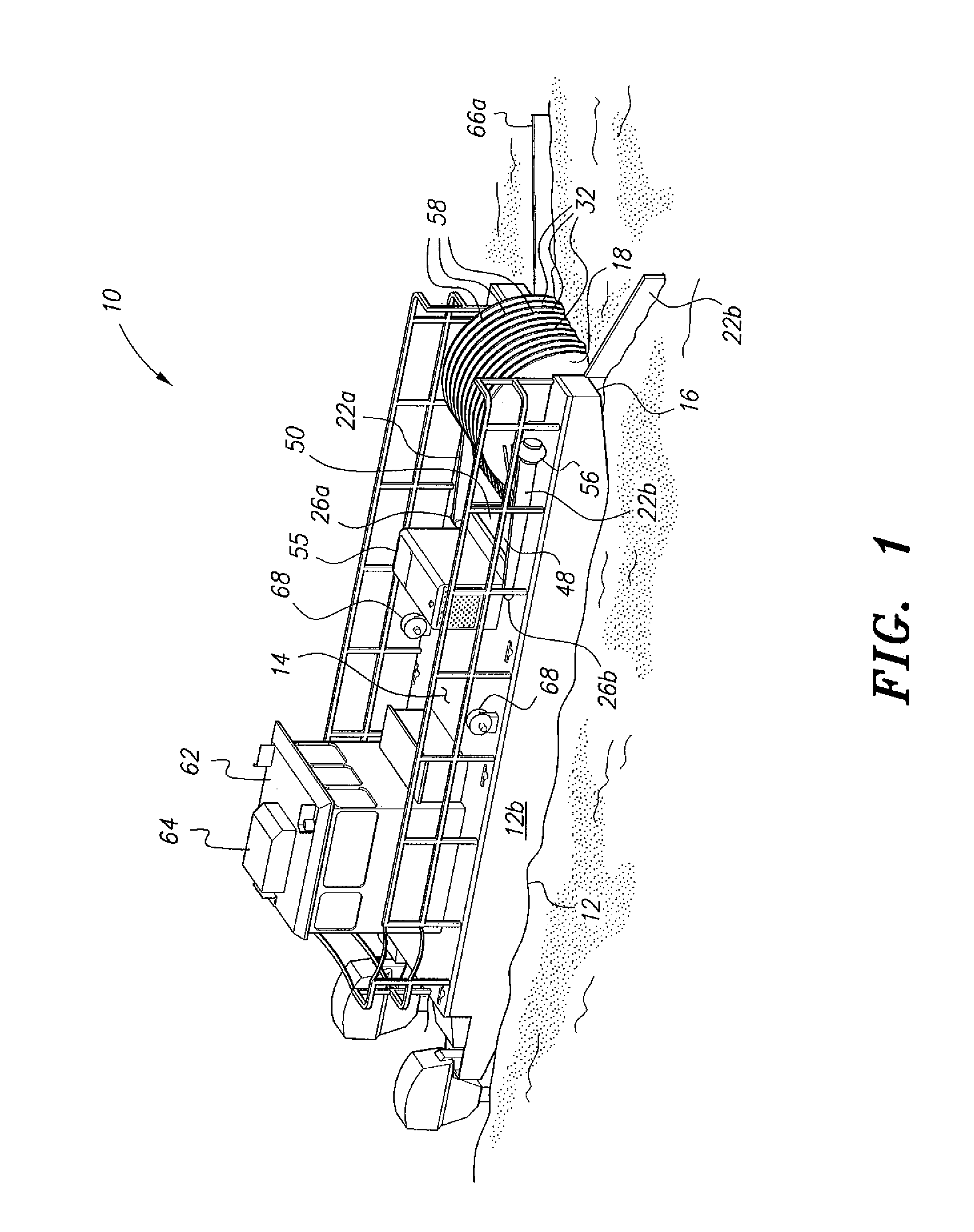
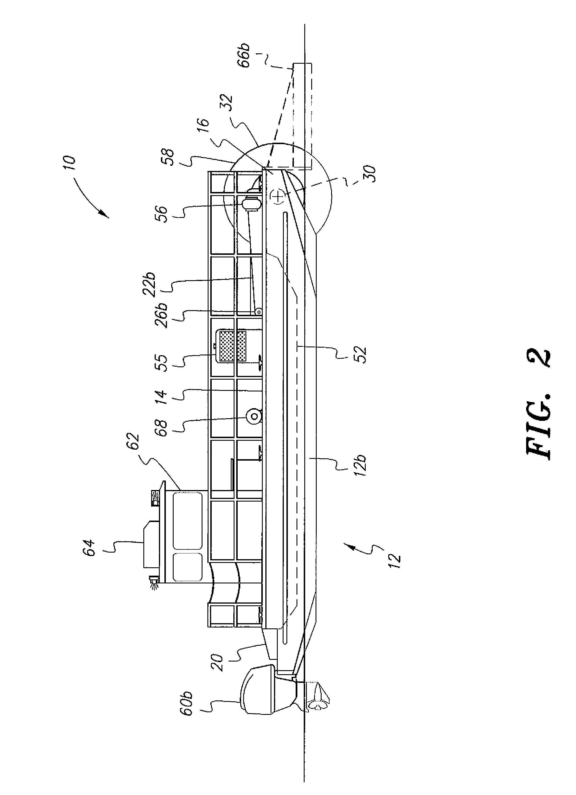
[0022]The oil spill recovery vessel is particularly adapted for the recovery of crude oil (or other liquids floating on the surface of a body of water) from the surface of a shallow body of water. The oil recovery mechanism articulates to rise when encountering a shallow obstruction, thereby allowing the vessel to function in shallower water than conventional oil recovery vessels.

[0023]FIGS. 1 through 3 provide environmental perspective, right side elevation, and top plan views, respectively, of the oil spill recovery vessel 10. The vessel 10 has a catamaran-type hull 12, i.e., having port and starboard hull units 12a and 12b, and a deck 14 spanning the two hull units. The hull 12 has a forward end 16 defining a laterally disposed oil recovery bay 18, and an opposite aft end 20 where the propulsion unit(s) is / are situated.

[0024]The oil recovery assembly articulates on laterally spaced first and second axle support arms 22a and 22b. Each arm 22a, 22b has a rearwardly disposed attachm...


PUM


Abstract

The oil spill recovery vessel is configured particularly for operations in relatively shallow water. The vessel is of catamaran configuration, with a large number of slowly rotating discs installed on a lateral rotary axle at the bow of the vessel. A wiper bears against each of the two surfaces of each disc, with oil residue running along the wipers being collected in a holding tank or tanks on the vessel. The oil may be pumped to other storage vessels or containers. The lateral axle on which the discs are installed is free to rise upward in the event that the discs contact a solid object or a shallow bottom. Thus, the discs are of relatively large diameter to provide relatively greater surface area across the surface of the water than is the case with vessels operating with smaller diameter discs.

Description

CROSS-REFERENCE TO RELATED APPLICATION[0001]This application claims the benefit of U.S. Provisional Patent Application Ser. No. 61 / 370,413, filed Aug. 3, 2010.BACKGROUND OF THE INVENTION[0002]1. Field of the Invention[0003]The present invention relates generally to vessels and equipment configured for environmental cleanup work, and particularly to an oil spill recovery vessel that provides a seagoing vessel configured for recovering crude oil or the like from the surface of a body of water.[0004]2. Description of the Related Art[0005]The development of technology permitting the drilling of oil and natural gas wells beneath the surface of the sea has greatly expanded the field of energy recovery. While the recovery of such oil and natural gas deposits has served to expand and continue the availability of energy produced by such deposits, this technology is not without its potential problems.[0006]When an oil well blowout or spill occurs on land, it is generally relatively easy to co...

Claims


Application Information

Patent Timeline
IPC IPC(8): E02B15/04C02F1/40
CPCC02F1/40E02B15/102C02F2103/007C02F2101/32Y02A20/204
Inventor LANCASTER, DAVID W.
Owner LANCASTER DAVID W
Why Eureka
Try Eureka