Light-collecting device, light-collecting device group, and solid-state imaging apparatus

a technology of light-collecting devices and solid-state imaging apparatus, which is applied in the field of light-collecting devices, can solve the problems of inability to realize a limited structure, and achieve the effects of preventing distortion, stable production, and decreasing yield

Active Publication Date: 2012-02-09
PANASONIC CORP
View PDF0 Cites 5 Cited by
  • Summary
  • Abstract
  • Description
  • Claims
  • Application Information

AI Technical Summary

Benefits of technology

[0038]A light-collecting device according to an aspect of the present invention is provided with the above-described configuration and can be stably produced in normal steps of manufacturing a semiconductor device. With the light-collecting device, the shape of the first annular region is prevented from distorting and disappearing, and the yield decreasing and the characteristics variability due to the variability of the shape of the light-collecting device can also be prevented.

Problems solved by technology

However, if the configuration shown in FIG. 20B is realized with normal manufacturing steps of a semiconductor device, a following problem arises.
Accordingly, there arises a first problem that unlimitedly small structure cannot be realized.

Method used


Image

  • Light-collecting device, light-collecting device group, and solid-state imaging apparatus
  • Light-collecting device, light-collecting device group, and solid-state imaging apparatus
  • Light-collecting device, light-collecting device group, and solid-state imaging apparatus

Examples


embodiment 1

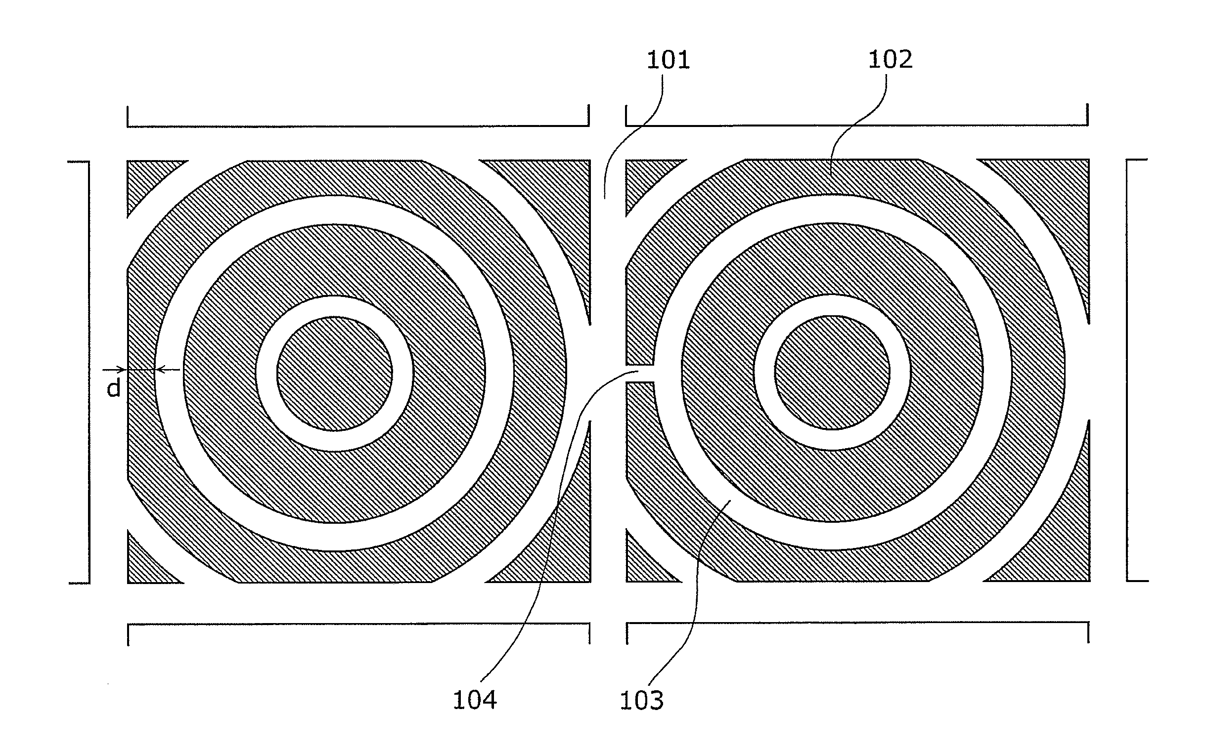
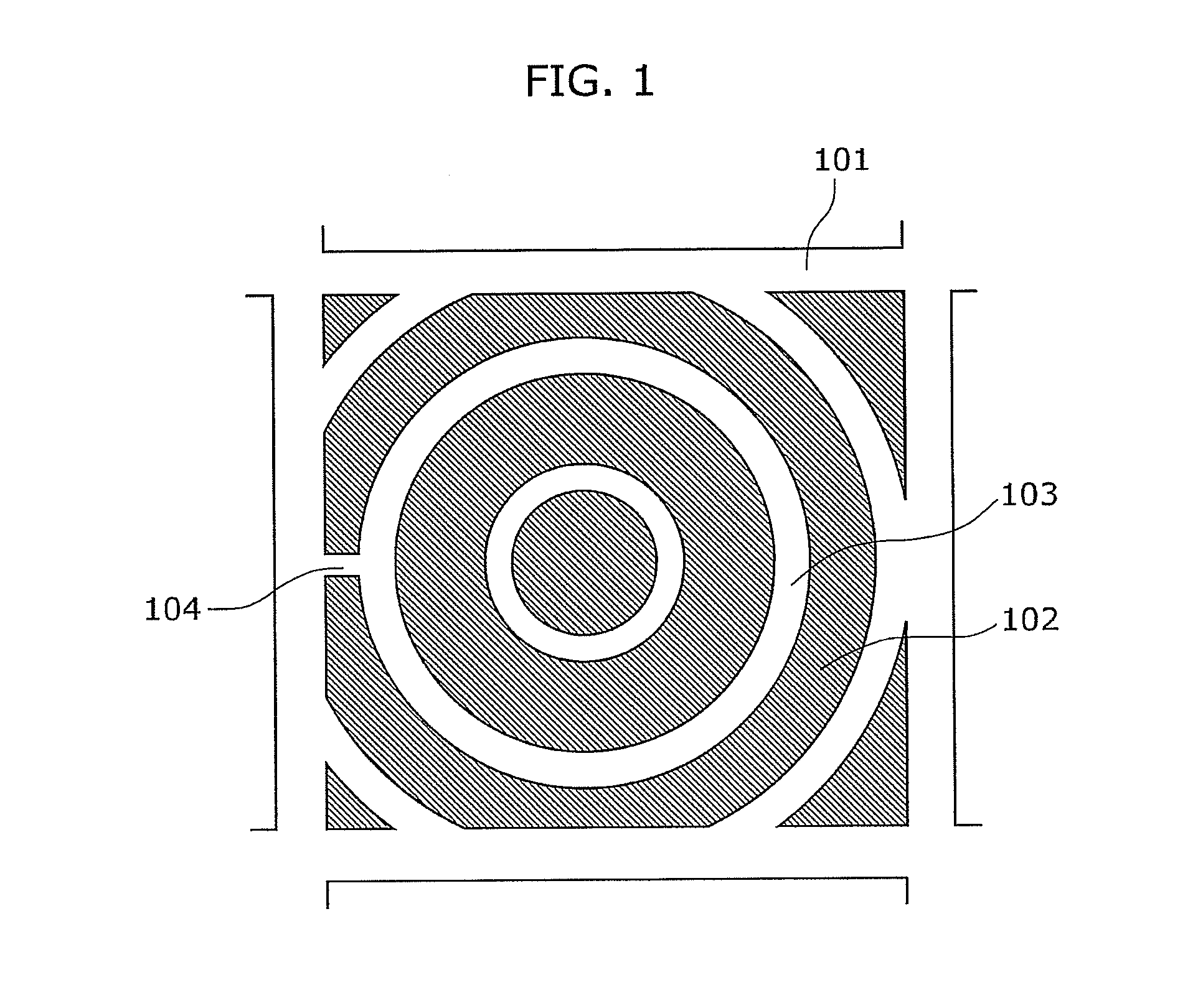
[0067]As for Embodiment 1, a configuration will be described in which a first annular region is made of a material having a high refractive index higher than that of air, a second annular region is formed by the air, and a gap is an air gap and connected to an adjacent one of the at least one second annular region.

[0068]FIG. 1 is a top view showing a configuration of a light-collecting device according to Embodiment 1 of the present invention. The light-collecting device in FIG. 1 is separated from adjacent other light-collecting devices by a pixel-end air gap 101, and includes a pixel-inside high refractive index portion 102 serving as the second annular region, a pixel-inside air gap 103 serving as the first annular region, and an air gap 104. The pixel-inside air gap 103 and the pixel-inside high refractive index portion 102 each have an approximately circular shape, and are concentrically arranged. The center of the concentric circles may correspond to the center of a pixel, or ...

embodiment 2

[0073]In Embodiment 1, an example is described in which air gap is provided as a gap in a first annular region, whereas an example will be described in which the gap is provided in a second annular region in Embodiment 2. In this case, the gap is filled with a high-refractive index material and connected to adjacent one of the at least one first annular region.

[0074]FIG. 3 is a top view showing a configuration of a light-collecting device according to Embodiment 2 of the present invention. The light-collecting device shown in FIG. 3 is different from that shown in FIG. 1 in that a gap 203 is provided instead of the air gap 104. The gap 203 has a convex shape projecting outward from a center of the light-collecting device, and is made of the high-refractive index material. The pixel-inside air gap 103 and the pixel-inside high refractive index portion 102 each have an approximately circular shape, and are concentrically arranged. The center of the concentric circles may correspond to...

embodiment 3

[0076]FIG. 4 is a top view showing a light-collecting device according to Embodiment 3 of the present invention. In FIG. 4, the pixel-inside air gap 103 and the pixel-inside high refractive index portion 102 each have an approximately circular shape, and are concentrically arranged.

[0077]In FIG. 4, the center of the concentric circles is displaced in an oblique direction with respect to the center of a pixel. In this case, the air gaps 104 are arranged in respective two portions as shown in FIG. 4, avoiding the light-collecting device from decreasing a size which cannot be produced in semiconductor manufacturing steps.


PUM


Abstract

A light-collecting device includes at least one first annular region having a first refractive index, and at least one second annular region having a second refractive index different from the first refractive index, the at least one first annular region and the at least one second annular region are adjacently and alternately arranged in a concentric manner, and at least one of the at least one first annular region and the at least one second annular region includes a gap at a portion where a width of the annular region gradually decreases.

Description

CROSS REFERENCE TO RELATED APPLICATION(S)[0001]This is a continuation application of PCT application No. PCT / JP2010 / 002801 filed on Apr. 19, 2010, designating the United States of America.BACKGROUND OF THE INVENTION[0002](1) Field of the Invention[0003]The present invention relates to light-collecting devices, in particular, to a light-collecting device in which a first annular region and a second annular region each having a refractive-index different from each other are adjacently and alternately arranged in a concentric manner, to a light-collecting device group, and to a solid-state imaging apparatus including the light-collecting device group.[0004](2) Description of the Related Art[0005]An apparatus which converts an image into an electrical signal (the apparatus is called an imaging apparatus) is typically used in equipment electromagnetically recording an image, including digital video recorders, digital still cameras, and camera-equipped cell-phones which are rapidly increa...

Claims


Application Information

Patent Timeline
Patent Type & Authority Applications(United States)
IPC IPC(8): H04N5/335G02B3/00H01L27/14H04N5/369H04N5/372H04N5/374
CPCG02B3/06G02B5/1885H01L31/0232H01L27/14623H01L27/14627G02B5/201H01L31/02327H01L31/02325
Inventor ISHII, MOTONORI
Owner PANASONIC CORP
Why Eureka
Try Eureka