Optical Information-Reading Apparatus and Optical Information-Reading Method

a technology of optical information and optical information, applied in the field of optical information-reading apparatus and optical information-reading method, can solve the problems of image recognition mistaken recognition, inability to identify the position of images, etc., and achieve the effects of reliably recognizing images, increasing image processing speed, and recognizing images reliably

Active Publication Date: 2012-02-09
OPTO ELECTONICS CO LTD
View PDF4 Cites 8 Cited by
  • Summary
  • Abstract
  • Description
  • Claims
  • Application Information

AI Technical Summary

Benefits of technology

[0023]Since the binarization threshold value is calculated for every block from the maximum and minimum values of the brightness values in the image data to binarize the brightness value, it becomes possible to recognize the image reliably even when the image is unclean or external disturbance light irradiates the image. Further, since the extreme-values-grouping means and the cluster-of-groups-selecting means are provided in order to identify the position of the code symbol, it becomes possible to identify the position of the code symbol.
[0024]With the optical information-reading apparatus and the optical information-reading method embodying the invention, it is possible to recognize the image reliably and to increase the speed of image processing. Further, since it is possible to identify the position of the code symbol, it is possible to recognize the code symbol more reliably. As a result thereof it is possible to provide an optical information-reading apparatus which has a low-cost and high performance.

Problems solved by technology

It is also impossible to identify the position of the image.
This causes the image to be recognized mistakenly.

Method used


Image

  • Optical Information-Reading Apparatus and Optical Information-Reading Method
  • Optical Information-Reading Apparatus and Optical Information-Reading Method
  • Optical Information-Reading Apparatus and Optical Information-Reading Method

Examples


first embodiment

Configuration Example of Code Scanner 1

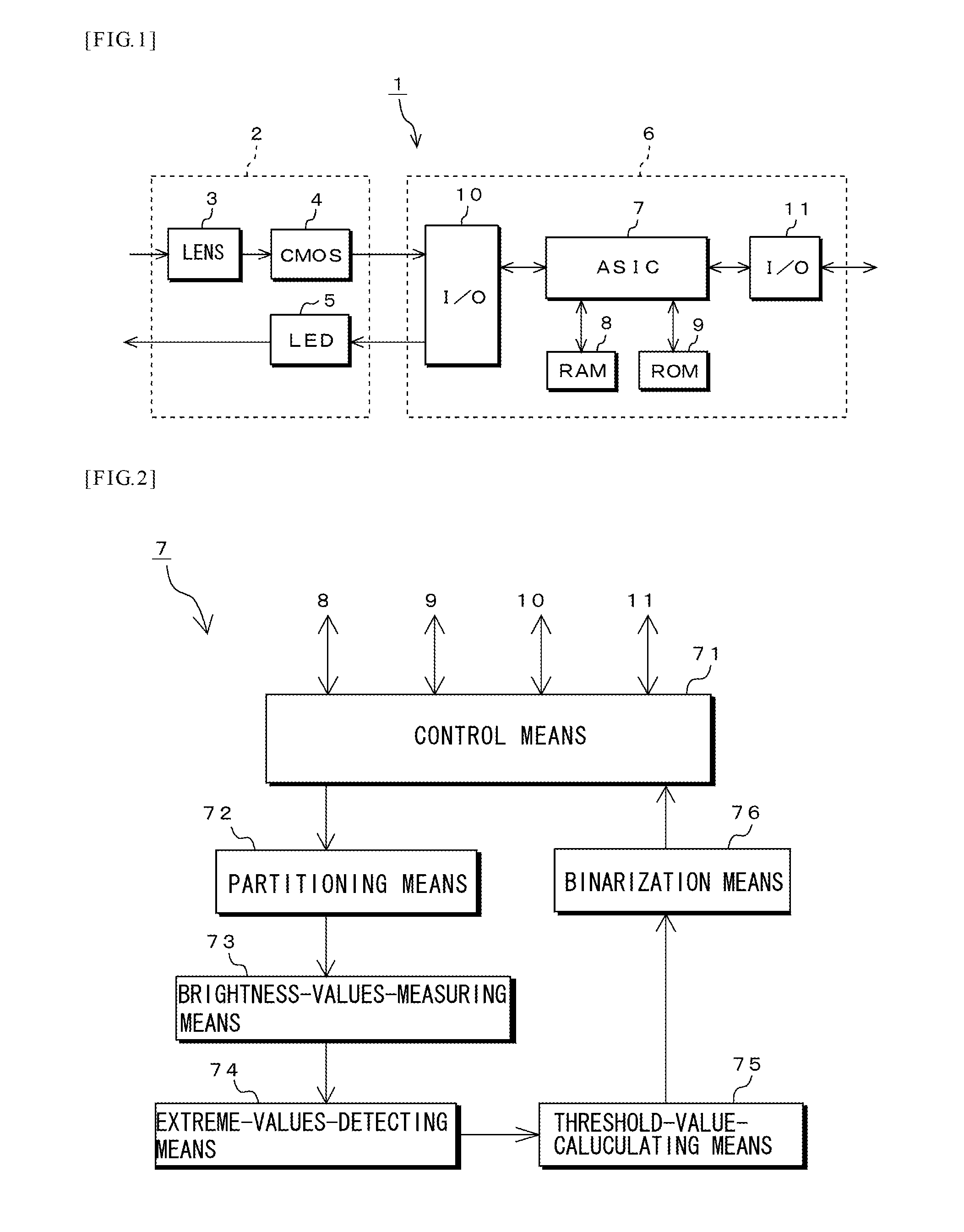
[0041]As shown in FIG. 1, the code scanner 1 according to this embodiment is composed of an optical head portion 2 and a decoder portion 6. The optical head portion 2 is provided with a lens 3 and a CMOS image sensor (hereinafter referred to as “CMOS 4”) which is an example of a solid-state image sensing device. Further, the optical head portion 2 has LED 5 which is an example of optical source.

[0042]The lens 3 is, for example, an optical lens and captures a code symbol, which is an image such as a two-dimensional code, not shown, in the optical head portion 2. CMOS 4 is provided on the lens 3. CMOS 4 images the code symbol that the lens 3 captures, converts the imaged code symbol from analog code symbol data to code symbol data which is represented by a digital brightness value, and outputs it to the decoder portion 6.

[0043]LED 5 is provided near the lens 3. LED 5 is controlled by ASIC 7, which will be described later, so as to be lighted. LED...

second embodiment

[0075]In this embodiment, there will be described ASIC 7A which is provided with an extreme-values-detecting means 74A removing a noise from the brightness values. Since elements having names and signs like those of the above-mentioned embodiment have like functions, the explanation thereof will be omitted.

Configuration Example of ASIC 7A

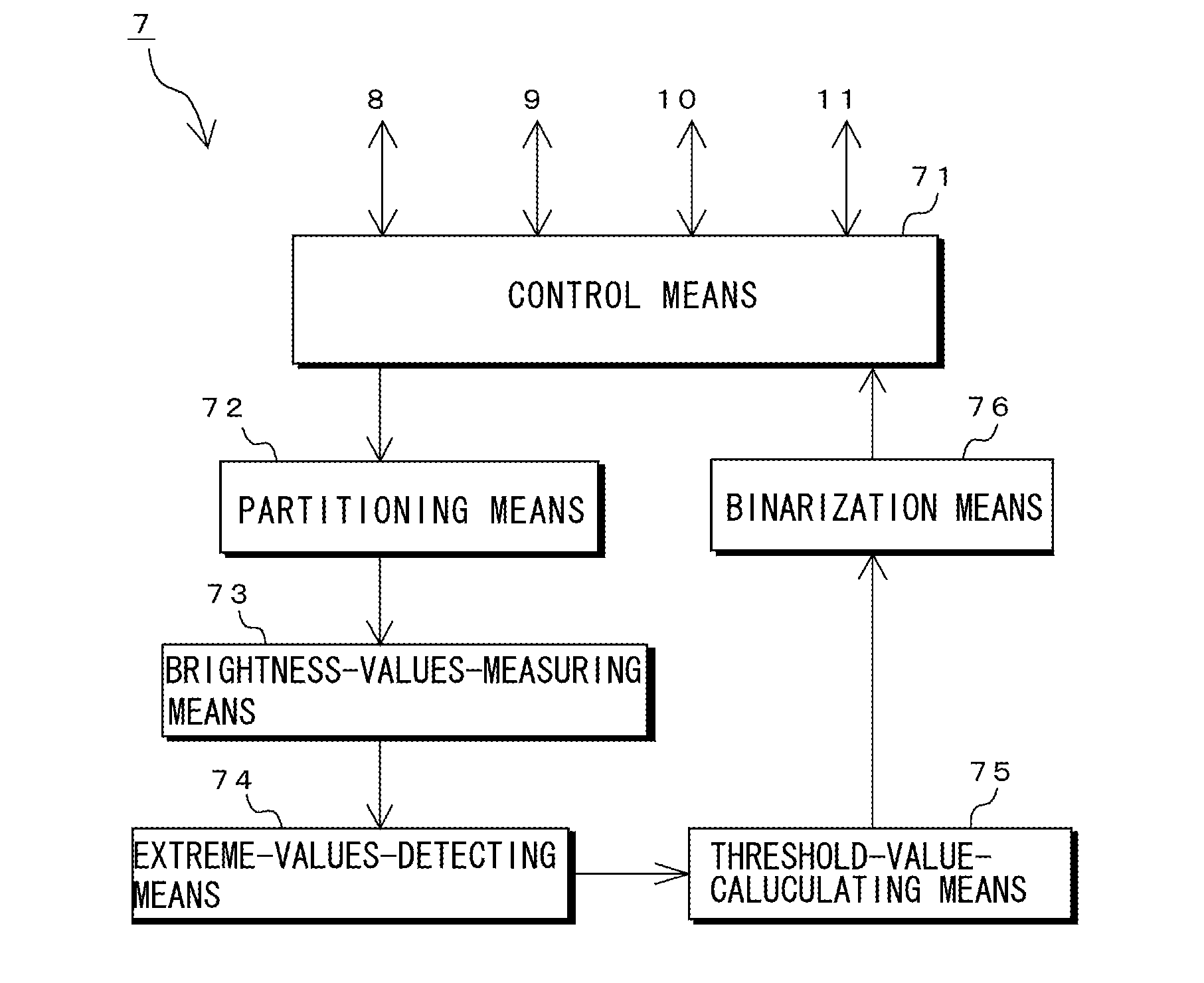
[0076]As shown in FIG. 8, ASIC 7A according to this embodiment has a control means 71, a partitioning means 72, a brightness-values-measuring means 73, an extreme-values-detecting means 74A, a threshold-value-calculating means 75 and a binarization means 76.

[0077]The extreme-values-detecting means 74A is provided between the brightness-values-measuring means 73 and the threshold-value-calculating means 75. The extreme-values-detecting means 74A has a function to detect the extreme values like the above-mentioned extreme-values-detecting means 74 and a function to remove any noise from the code symbol data captured by the decoder portion 6.

[0078]FIG....

third embodiment

[0090]In this embodiment, there will be described ASIC 7B which identifies the position of the code symbol. Since elements having names and signs like those of the above-mentioned embodiments have like functions, the explanation thereof will be omitted.

Configuration Example of ASIC 7B

[0091]As shown in FIG. 12, ASIC 7B according to this embodiment has a control means 71, a partitioning means 77, a brightness-values-measuring means 73, an extreme-values-detecting means 74A, a threshold-value-calculating means 75 a binarization means 76, an extreme-values-grouping means 77 and a groups-selecting means 78.

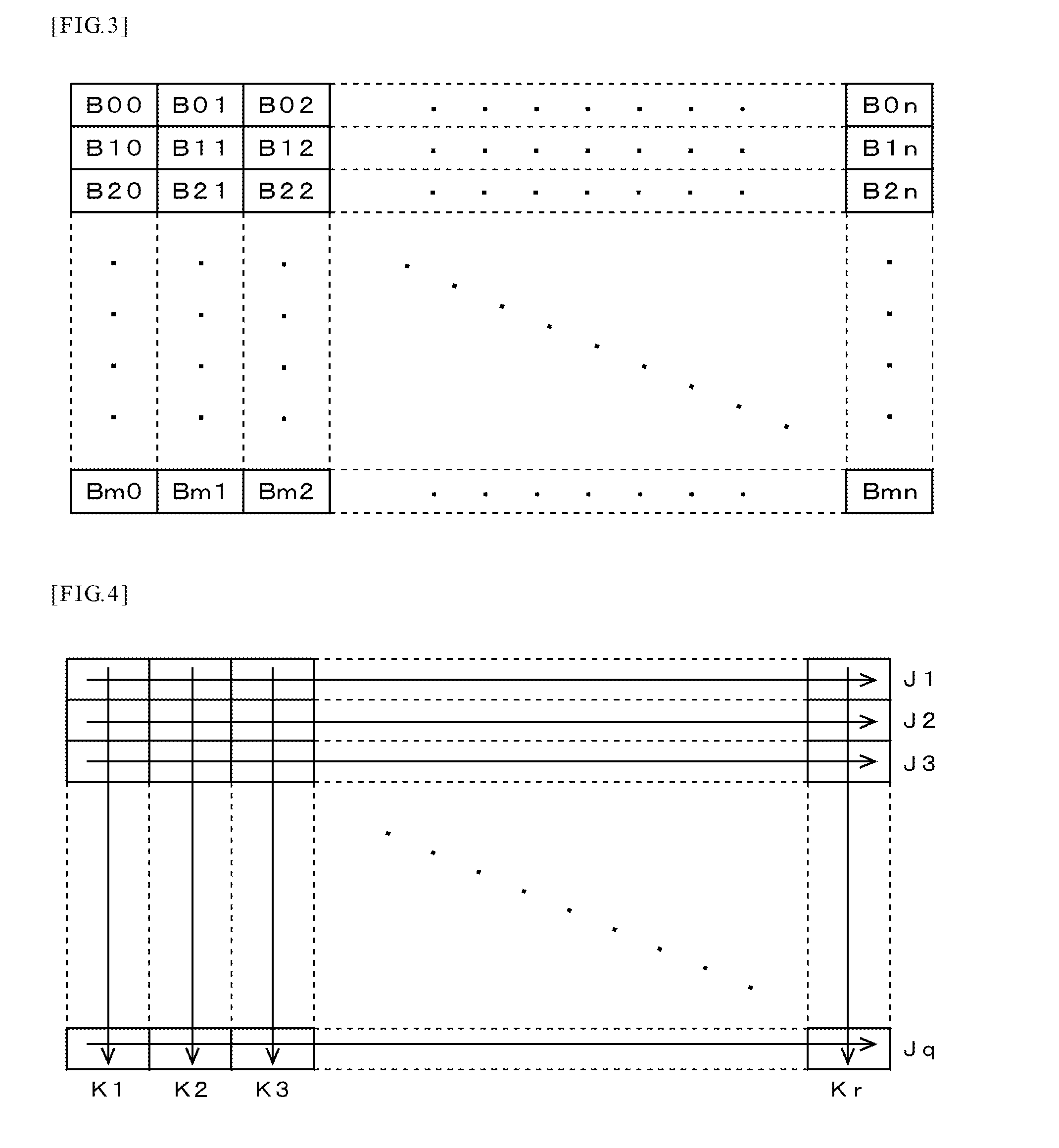
[0092]To the threshold-value-calculating means 75, the extreme-values-grouping means 77 is connected. The extreme-values-grouping means 77 counts the blocks partitioned by the partitioning means 72, determines whether or not there is a threshold value in the counted block and if there is a threshold value, groups adjacent blocks, in which there is a threshold value, to generate groups....


PUM


Abstract

A method and apparatus to enable a position of an image to be identified and to enable the image to be recognized reliably even when the image is unclean or external disturbance light is irradiates the image. On a assumption that a binarization threshold value is calculated for every block based on the maximum and minimum values of the brightness values in code symbol data, plural adjacent blocks, the threshold values of which are calculated, are grouped to generate groups. The area of each of the groups thus generated is compared with a predetermined area for a comparison standard and if the area of each of the groups thus compared is larger than that, these groups are selected. The position of the selected groups is identified. Brightness value of the code symbol data are binarized using the threshold value for every block in the selected groups.

Description

[0001]This patent application is a continuation of International Application No. PCT / JP2010 / 055265 filed Mar. 25, 2010 and designating the United States of America. This international application was published in Japanese on Sep. 3, 2010 under No. WO 2010 / 110385 A1. This international application is hereby incorporated by reference in its entirety.BACKGROUND ART OF THE INVENTION[0002]The present invention relates to an optical information-reading apparatus such as a code scanner, an optical character reader (OCR), or the like, and an optical information-reading method.[0003]A bar code has been used previously for merchandise control, stock management, or the like. As a code symbol that has more increased information density than this bar code, there have been two-dimensional codes such as Data Matrix, QR code, PDF417, Maxi Code, and the like. An apparatus for reading these two-dimensional codes captures the two-dimensional codes with a solid-state image sensing device such as a CMOS...

Claims


Application Information

Patent Timeline
Patent Type & Authority Applications(United States)
IPC IPC(8): G06K9/20G06K9/40
CPCG06K7/1478
Inventor LIU, SHIPING
Owner OPTO ELECTONICS CO LTD
Why Eureka
Try Eureka