Mitral Prosthesis and Methods for Implantation

a technology of mitral valve and prosthesis, which is applied in the field of artificial heart valve prosthesis, can solve the problems of traumatic procedures, high surgical risk, and many patients requiring mitral valve replacement, and achieve the effects of preventing valve migration, minimizing peri-valvular leakage, and maintaining valve stability

Active Publication Date: 2012-02-09
MEDTRONIC VENTOR TECH
View PDF8 Cites 420 Cited by
  • Summary
  • Abstract
  • Description
  • Claims
  • Application Information

AI Technical Summary

Benefits of technology

[0007]Provided herein is a mitral valve prosthesis and methods for implanting the prosthesis transapically (i.e., through the apex of the heart), transatrially (i.e., through the left atrium of the heart), and transseptally (i.e., through the septum of the heart). The prosthesis generally includes a self-expanding frame and two or more support arms. A valve prosthesis is sutured to the self-expanding frame. Each support arm corresponds to a native mitral valve leaflet. One or more support arms act to immobilize the native leaflets, and hold the native leaflets close to the frame. Such configuration achieves numerous goals. For example, such configuration can: prevent the native leaflets from obstructing flow through the left ventricular outflow tract (LVOT); prevent the native leaflets from interacting with the prosthetic leaflets; recruit the native leaflets in minimizing peri-valvular leaks; maintain proper alignment of the valve prosthesis; avoid systolic anterior mobility; and maintain valve stability by preventing migration of the valve into the atrium or ventricle. The design of the prosthesis also mimics the native valve and supports a non-round in vivo configuration, which better reflects native valve function.
[0008]The prosthesis is generally designed to include two or more commissural posts that are relatively parallel with and level to the ends of the prosthetic valve leaflets, which prevents interaction between the prosthesis and the LVOT and / or native aortic valve. The prosthesis is also generally designed such that diverging commissures are not required because the orifice area is sufficiently large and pressure recovery is not a concern. The inlet end of the prosthesis is wider than the valve segment at the native annular level to prevent migration into the ventricle and to improve sealing of the valve against the atrial wall. The inlet end of the prosthesis may also be designed asymmetrically to accommodate the anterior horn of the atrium, which is associated anatomically with the position of the aortic valve. Fixation barbs at the level of the inlet may provide further fixation to prevent device migration into the ventricle.

Problems solved by technology

Such procedures are traumatic.
Further, similar to aortic valve replacement, many patients requiring mitral valve replacement are inoperable or deemed to pose high surgical risk.

Method used


Image

  • Mitral Prosthesis and Methods for Implantation
  • Mitral Prosthesis and Methods for Implantation
  • Mitral Prosthesis and Methods for Implantation

Examples


Embodiment Construction

[0023]The following detailed description of mitral valve prostheses and methods for implantation refers to the accompanying figures that illustrate exemplary embodiments. Other embodiments are possible. Modifications can be made to the embodiments described herein without departing from the spirit and scope of the present invention. Therefore, the following detailed description is not meant to be limiting.

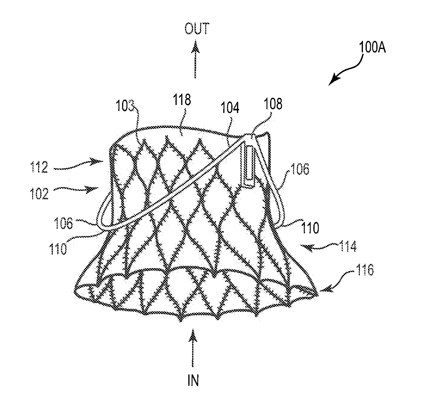
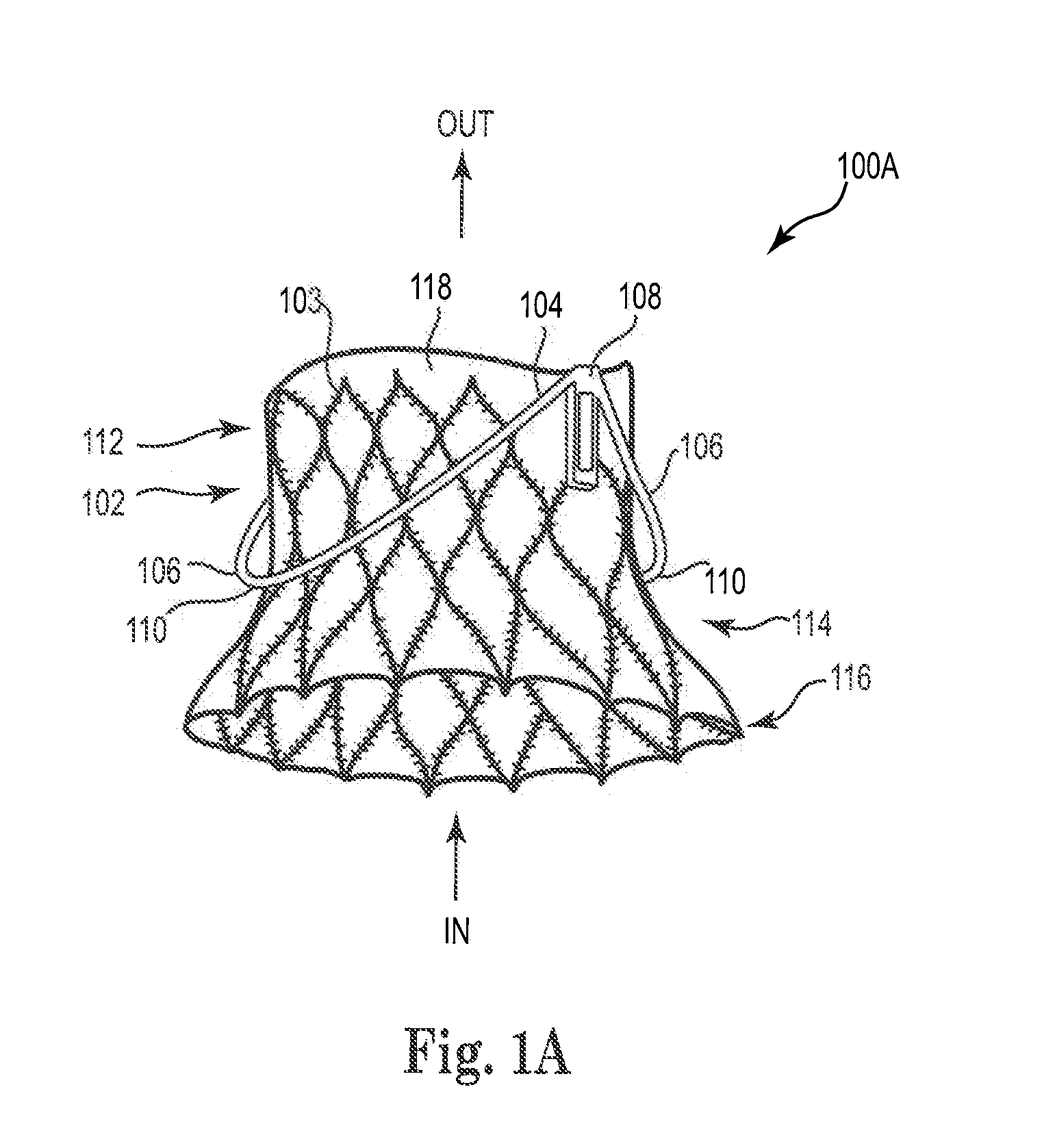
[0024]FIG. 1A is a perspective view of a mitral valve prosthesis 100A, in accordance with one embodiment presented herein. Mitral valve prosthesis 100A includes an inner support structure (or main frame) 102 and an outer support structure 104. Outer support structure 104 includes outer engagement arms (or outer support arms) 106. As shown, mitral valve prosthesis 100A includes two outer engagement arms 106 to anatomically match the native mitral valve leaflets. Upon implantation outer engagement arms 106 clamp and immobilize the native mitral valve leaflets, and hold the native lea...


PUM

PropertyMeasurementUnit
diameteraaaaaaaaaa
cross-sectional areaaaaaaaaaaa
stabilityaaaaaaaaaa

Abstract

A mitral valve prosthesis and methods for implanting the prosthesis transapically (i.e., through the apex of the heart), transatrially (i.e., through the left atrium of the heart), and transseptally (i.e., through the septum of the heart). The prosthesis generally includes a self-expanding frame and two or more support arms. A valve prosthesis is sutured to the self-expanding frame. Each support arm corresponds to a native mitral valve leaflet. At least one support arm immobilizes the native leaflets, and holds the native leaflets close to the main frame.

Description

CROSS REFERENCE TO RELATED APPLICATIONS[0001]This application claims benefit under 35 U.S.C. 119(e) to U.S. Provisional Patent Application 61 / 307,743, filed Feb. 24, 2010, which is incorporated by reference herein in its entirety.BACKGROUND OF THE INVENTION[0002]1. Field of the Invention[0003]The present invention is related to artificial heart valves. More specifically, the present invention is directed to an artificial mitral valve prosthesis and methods of implanting the prosthesis.[0004]2. Background Art[0005]The mitral valve exhibits two types of pathologies: regurgitation and stenosis. Regurgitation is the more common of the two defects. Typically, either defect is treated by a surgical repair. Under certain condition, however, the mitral valve must be replaced. Standard approaches to mitral valve replacement require cutting open the left side of the heart to access the native mitral valve. Such procedures are traumatic. Further, similar to aortic valve replacement, many patie...

Claims


Application Information

Patent Timeline
Patent Type & Authority Applications(United States)
IPC IPC(8): A61F2/24
CPCA61F2/2418A61F2/2436A61F2002/8483A61F2250/0039A61F2250/006A61F2220/0016A61F2230/0013A61F2230/0078A61F2220/0075A61F2230/0006A61F2230/0069A61F2/2412A61F2210/0004A61F2/24A61F2/2409
Inventor TUVAL, YOSI
Owner MEDTRONIC VENTOR TECH
Why Eureka
Try Eureka