Valve Prosthesis and Method for Delivery

Active Publication Date: 2014-07-10
MEDTRONIC INC
View PDF2 Cites 179 Cited by
  • Summary
  • Abstract
  • Description
  • Claims
  • Application Information

AI Technical Summary

Benefits of technology

[0012]Provided herein are mitral valve prostheses and methods for implanting the prostheses in the heart. The prostheses generally include a self-expanding frame and two or more support arms. A valve prosthesis is sutured to the self-expanding frame. Each support arm corresponds to a native mitral valve leaflet. At least one support arm immobilizes the native leaflets, and holds the native leaflets close to the main frame. Such configuration achieves numerous goals. For example, such configuration achieves one or more of the following: prevents the native leaflets from obstructing flow through the left ventricular outflow tract (LVOT); prevents the native leaflets from interacting with the prosthetic leaflets; recruits the native leaflet

Problems solved by technology

However, surgical procedures can lead to an interruption of the mitral annulus-papillary muscle continuity, which accounts for changes in geometry mechanics and performance of the left ventricle.
These problems are lessened by the emerging techniques for minimally invasive mitral valve repair, but still many of those techniques require arresting the heart and funneling the blood through a heart-lung machine, which can also be traumatic for patients.
Such procedures are traumatic to the patient, require a long recovery time, and can result in life threatening complications.
Therefore, many patients requiring cardiac valve replacement are deemed to pose too high a risk

Method used


Image

  • Valve Prosthesis and Method for Delivery
  • Valve Prosthesis and Method for Delivery
  • Valve Prosthesis and Method for Delivery

Examples


Example

[0034]The following detailed description of a valve prosthesis and valve prosthesis frame refers to the accompanying figures that illustrate exemplary embodiments. Other embodiments are possible. Modifications can be made to the embodiments described herein without departing from the spirit and scope of the present invention. Therefore, the following detailed description is not meant to be limiting.

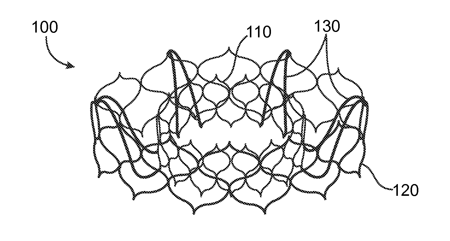
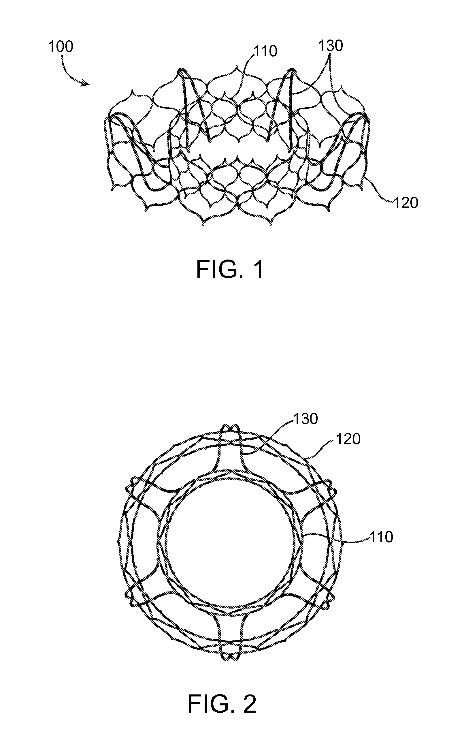
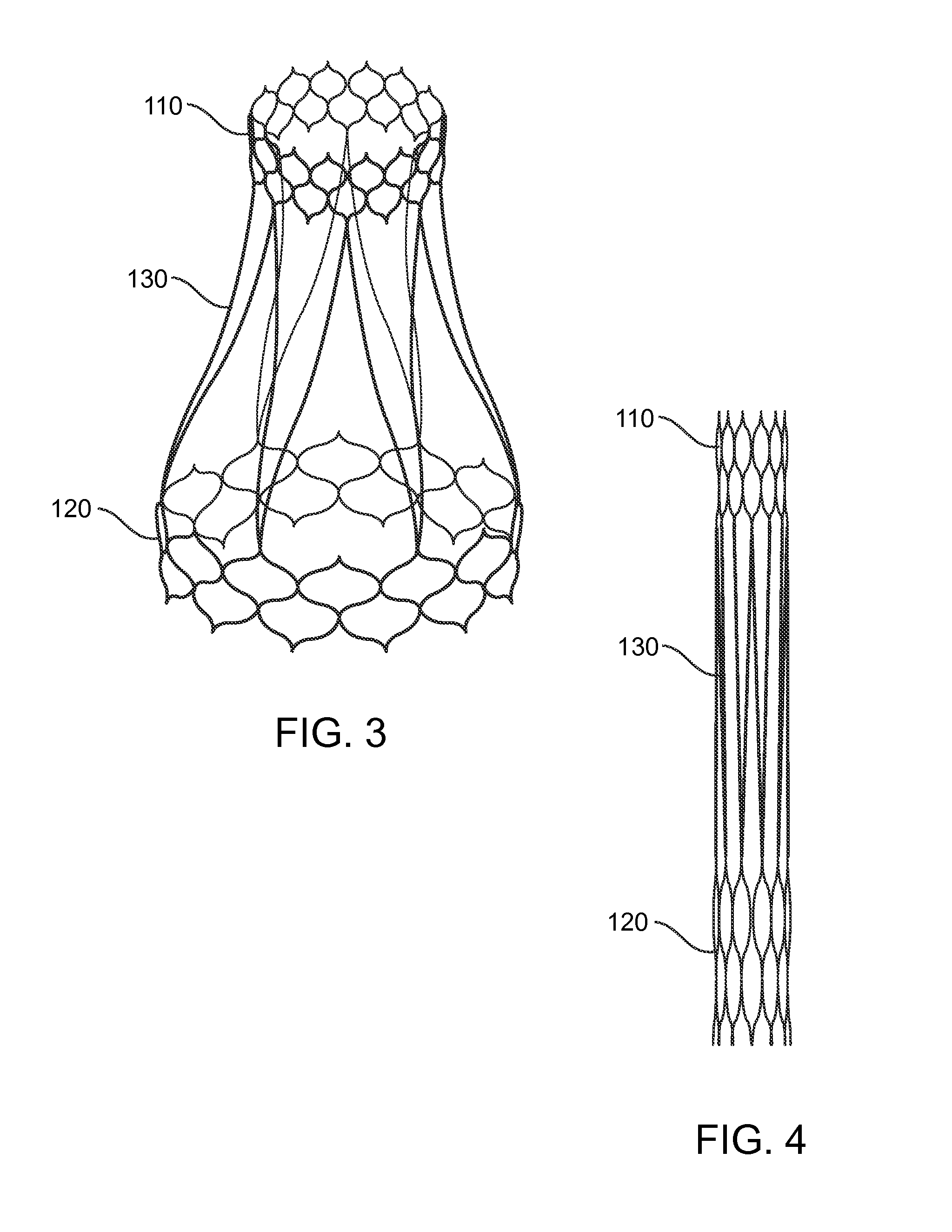
[0035]The present invention is directed to a heart valve prosthesis having a self-expanding frame that supports a valve body. The valve prosthesis can be delivered percutaneously to the heart to replace the function of a native valve. For example, the valve prosthesis can replace a bicuspid or a tricuspid valve such as the aortic, mitral, pulmonary, or tricuspid heart valve. As used herein the term “distal” is understood to mean downstream to the direction of blood flow. The term “proximal” is intended to mean upstream to the direction of blood flow.

[0036]In one aspect of the invention, t...


PUM


Abstract

Heart valve prostheses are provided for replacing a cardiac valve. The heart valve prosthesis includes a self-expanding frame including a first portion and a second portion. In the collapsed configuration, the first portion is positioned adjacent to the second portion. In the expanded configuration, the first portion moves to be positioned within an interior area of the second portion.

Description

BACKGROUND OF THE INVENTION[0001]1. Field of the Invention[0002]The present invention is related to an artificial heart valve frame. More specifically, the present invention is directed to an artificial valve prosthesis.[0003]2. Background Art[0004]The mitral valve is a functional organ composed of multiple dynamically interrelated units. During cardiac cycle, the fibrous skeleton, the anterior and posterior leaflets, the papillary muscles, the chordae tendinea, and the ventricular and atrial walls all interplay to render a competent valve. The complex interaction between the mitral valve and the ventricle by the subvalvular apparatus (the papillary muscles and the chordae tendinea) is essential in maintaining the continuity between the atrio-ventricular ring (which is part of the fibrous skeleton of the heart) and the ventricular muscle mass, which provides for the normal functioning of the mitral valve.[0005]Cardiac valves, including the mitral valve, exhibit two types of patholog...

Claims


Application Information

Patent Timeline
IPC IPC(8): A61F2/24
CPCA61F2/2418A61F2230/0065A61F2250/0039A61F2250/006A61F2210/0061A61F2/2445
Inventor KOVALSKY, IGORHARITON, ILIATUVAL, YOSSIYELLIN, NADAV
Owner MEDTRONIC INC
Why Eureka
Try Eureka