Surgical instruments and methods

Inactive Publication Date: 2017-11-09
UNIV DE BARCELONA
View PDF0 Cites 0 Cited by
  • Summary
  • Abstract
  • Description
  • Claims
  • Application Information

AI Technical Summary

Benefits of technology

[0008]In a second aspect, a surgical implant for stabilising a lamina of a vertebra of a patient is provided. The implant comprises a mounting flange including a hole for accommodating a bone screw for attachment to articular process of the vertebra, and a first, a second and a third clamping flange. The first clamping flange is configured to be arranged on a first side of the lamina, and the second and third clamping flanges are configured to be arranged on a second side of the lamina, the second side being opposite to the first side, such that the lamina is clamped between the clamping flanges. The clamping flanges comprise one or more sharp stabilizers on surfaces that are in contact with the lamina and the second and third clamping flanges are laterally offset with respect to the first clamping flange. In accordance with this aspect, an implant is provided which is particularly suited for the surgical intervention described above. Clamping flanges are provided on either side of the lamina and due to the sharp stabilizers on the clamping flanges, no bone screws are necessary for fixing the implant to the laminae. The clamping flanges on one side can be laterally offset with respect to the clamping flange on the other side. This ensures a stable clamping of the lamina, and stable positioning of the lamina in spite of having only a single screw hole for attachment to the articular process. Risky procedures for attaching the implant to the laminae may thus be avoided, while stability of the laminae is maintained. In some examples, the inner clamping flange and/or the outer clamping flange are flexible such that their orientation with respect to the mounting flange is adjustable for fitting the clamping flanges on either side of the lamina. The flexibility of the clamping flanges enables relatively easy positioning of the flanges on either side of a lamina. In some examples, two outer clamping flanges and a single inner clamping flange is provided. Alternatively, two inner clamping flanges and a single outer clamping flange is provided. In these examples, stability of the lamina can be further improved. In another aspect, a surgical kit is provided. Such a kit may comprise a surgical implant substantially as hereinbefore described, and one or more bone screws for attachment of the implant to the articular process of the vertebra. Optionally, the surgical kit may further include a scalpel and/or an osteotome.
[0009]In another aspect, a scalpel for minimally invasive surgical procedures is provided. The scalpel comprises a longitudinal shaft having a proximal end and a distal end, with a grip being provided at the proximal end, and a dissector being provided at the distal end. The dissector comprises a first portion extending along a first direction generally corresponding to a direction of the distal end of the shaft, and a second portion extending along a second direction, wherein an angle between the second direction and the first direction is 90°-135°. The distal end of the second portion comprises a rounded tip. The dissector further comprises a cutting blade provided between the first portion and the second portion of the dissector, wherein a cutting edge of the cutting blade is arranged forming an acute angle with the first direction such that the scalpel can dissect and cut tissue in a single substantially straight movement. In accordance with this aspect, a scalpel is provided which can at the same time separate tissue and cut tissue.

Problems solved by technology

This narrowing causes a restriction of the spinal canal, resulting in a neurological deficit.
Symptoms can include pain, numbness, and loss of motor control.
Laminectomy may be an effective procedure for relieving pressure on spinal nerves, but may result in chronic back pain and weakness in a patient after the laminectomy.
A surgeon thus has to frequently change instruments, making the oper

Method used


Image

  • Surgical instruments and methods
  • Surgical instruments and methods
  • Surgical instruments and methods

Examples


Embodiment Construction

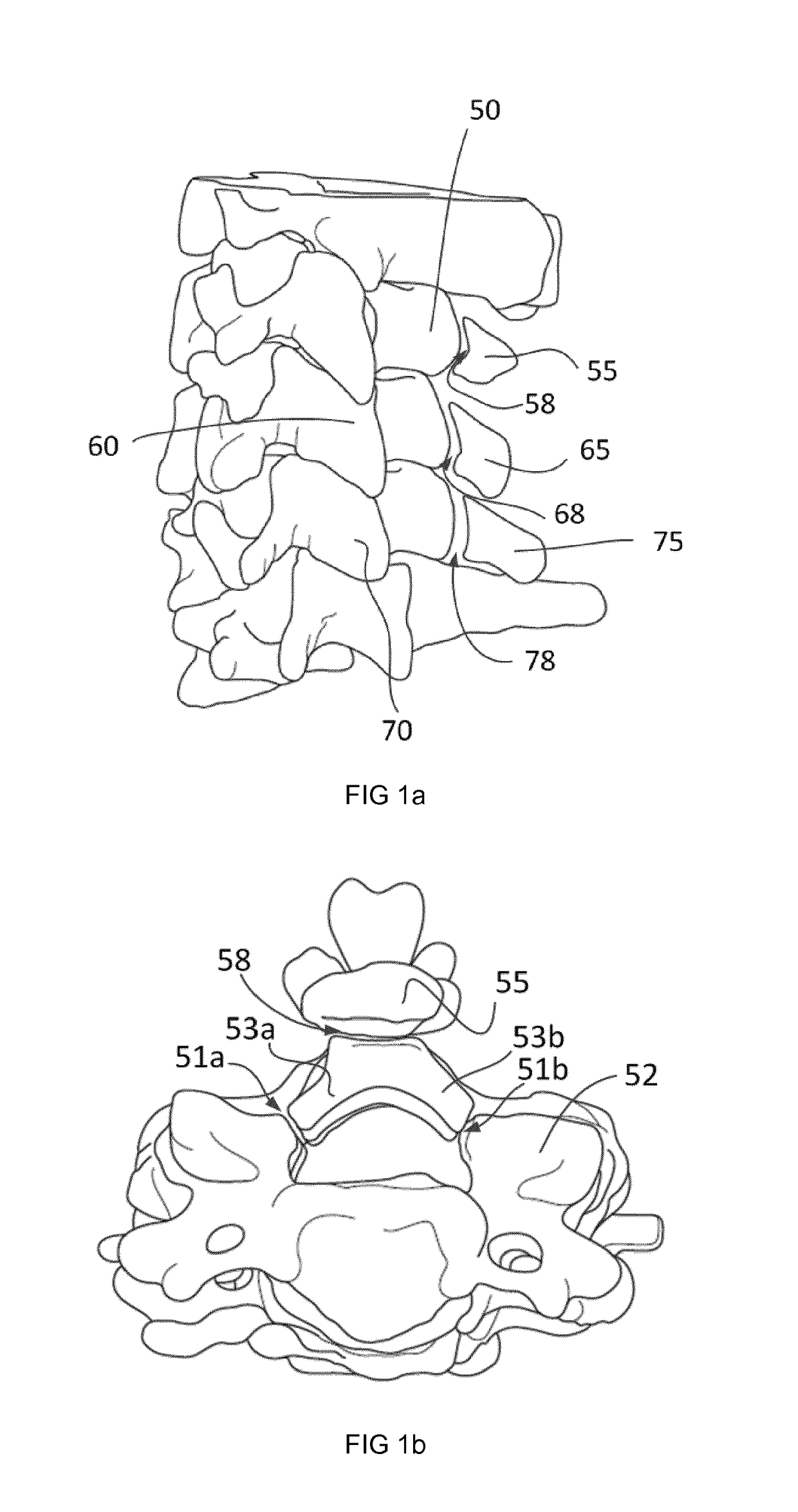
[0019]FIG. 1 illustrates various steps of an example of a method of surgical treatment of spinal stenosis. FIG. 1a illustrates three cervical vertebrae 50, 60, 70. In a first method step the “domes”55, 65, 75 or apical portions of the spinous process of vertebrae 50, 60, 70 are separated by removing a mid-portion of the spinous process. Removal of the mid-portion of the spinous process may be done using an osteotome adapted to cut in two planes simultaneously. Examples of such osteotomes are described later herein, particularly with reference to FIG. 6a-6e. In an example, approximately one third of the spinous process may be left attached to the laminae, approximately one third may be removed and approximately one third of the spinous process may form the apical portion.

[0020]In FIG. 1a, the separation of the apical portions 55, 65, and 75 from the base of the spinous process and the laminae is schematically illustrated with cuts 58, 68 and 78. In a subsequent step (FIG. 1a, right),...


PUM


Abstract

Laminoplasty methods for the treatment of spinal stenosis are disclosed, as well as surgical instruments and a surgical implant related to these methods. One of the surgical instruments is a scalpel for minimally invasive surgical procedure, including a longitudinal shaft, a grip and a dissector. Another instrument is an osteotome including two jaws being pivotable around a first axis and facing each other. The surgical implant is useful for stabilizing a lamina of a vertebra of a patient and comprises a mounting flange including a hole for accommodating a bone screw for attachment to an articular process of the vertebra, and three clamping flanges.

Description

[0001]The present disclosure relates to surgical interventions accessing the spinal canal, and in particular to methods of treating spinal stenosis. The present disclosure further relates to implants, surgical instruments and surgical kits used in such methods. The present disclosure further relates to scalpels, and in particular to scalpels for use in minimally invasive procedures.BACKGROUND ART[0002]Spinal stenosis is an abnormal narrowing (stenosis) of the spinal canal that can occur in regions of the spine. This narrowing causes a restriction of the spinal canal, resulting in a neurological deficit. Symptoms can include pain, numbness, and loss of motor control. There are several types of spinal stenosis, with lumbar stenosis and cervical stenosis being the most frequent. Spinal stenosis more frequently occurs in the elderly.[0003]One possible treatment of spinal stenosis includes surgery. The traditional technique for decompression of lumbar nerves is laminectomy, which is a su...

Claims


Application Information

Patent Timeline
IPC IPC(8): A61B17/70A61B17/80A61F2/28
CPCA61B17/7071A61B17/808A61F2/2846
Inventor PRATS GALINO, ALBERTOPEREIRA CARPIO, DAVID OTHONIEL
Owner UNIV DE BARCELONA
Why Eureka
Try Eureka