Valve Prosthesis

Active Publication Date: 2014-04-24
MEDTRONIC INC
View PDF0 Cites 10 Cited by
  • Summary
  • Abstract
  • Description
  • Claims
  • Application Information

AI Technical Summary

Benefits of technology

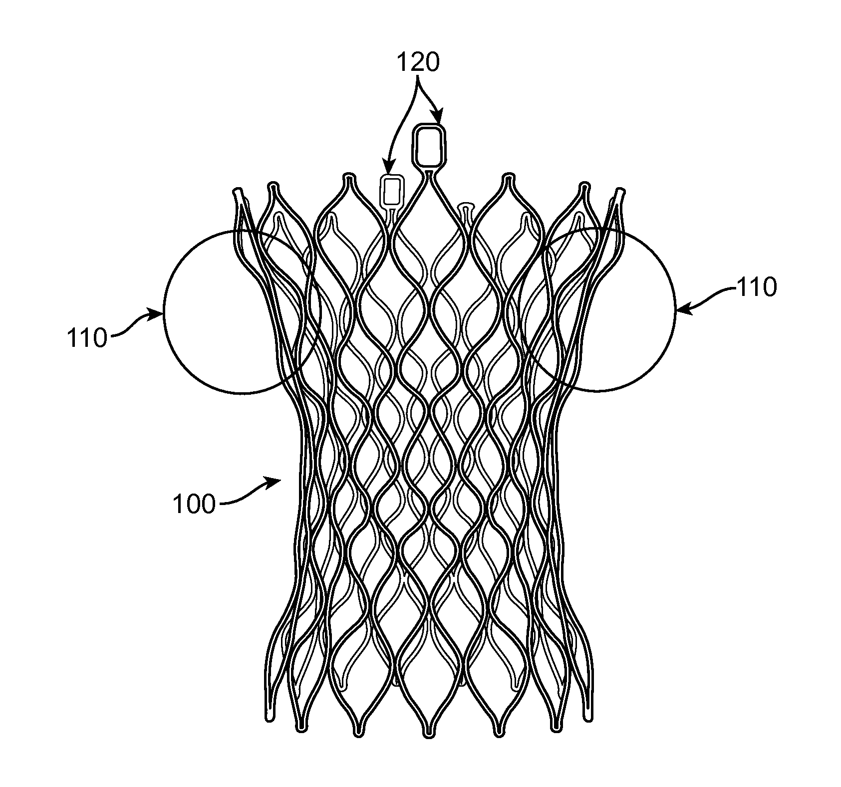
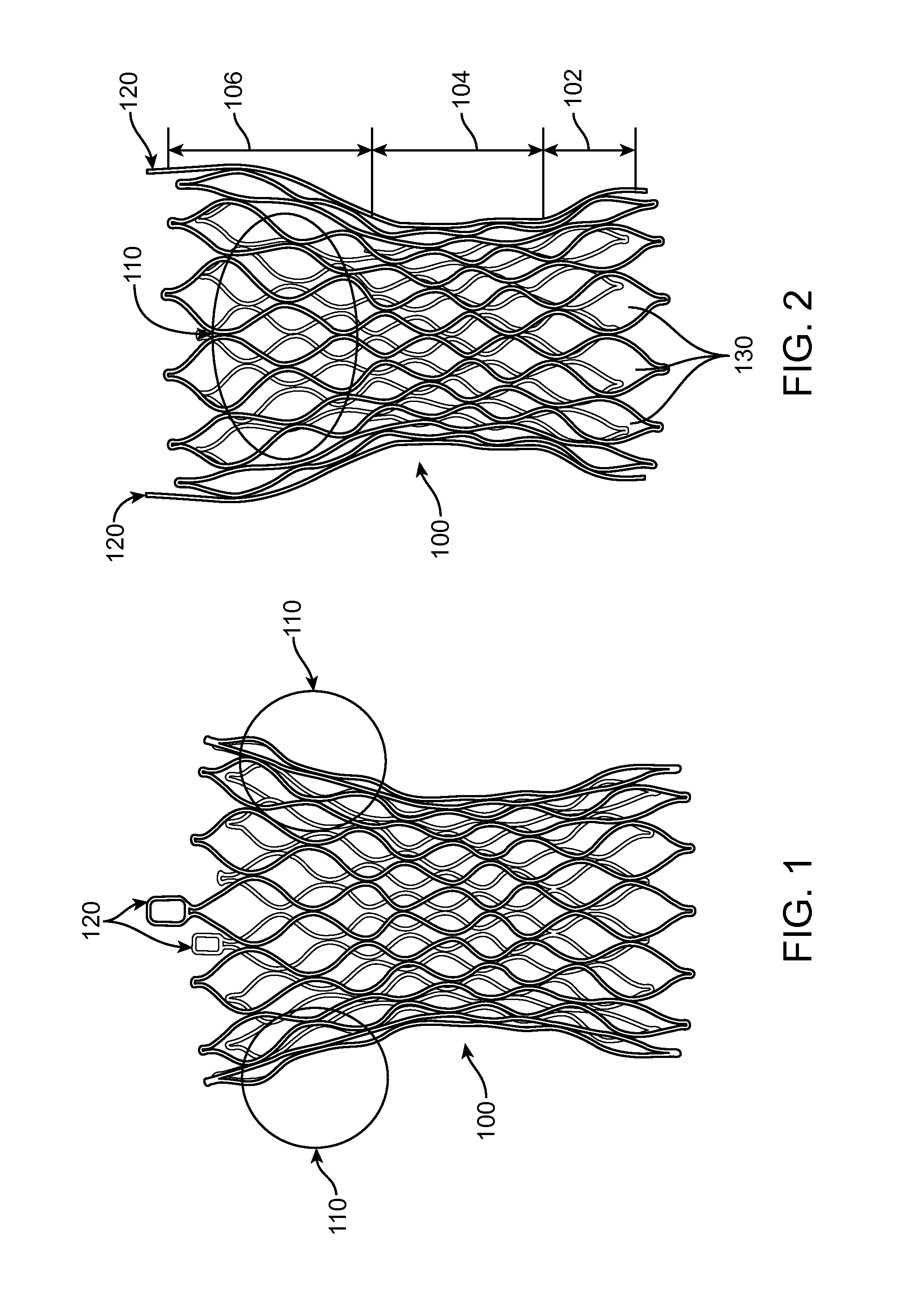
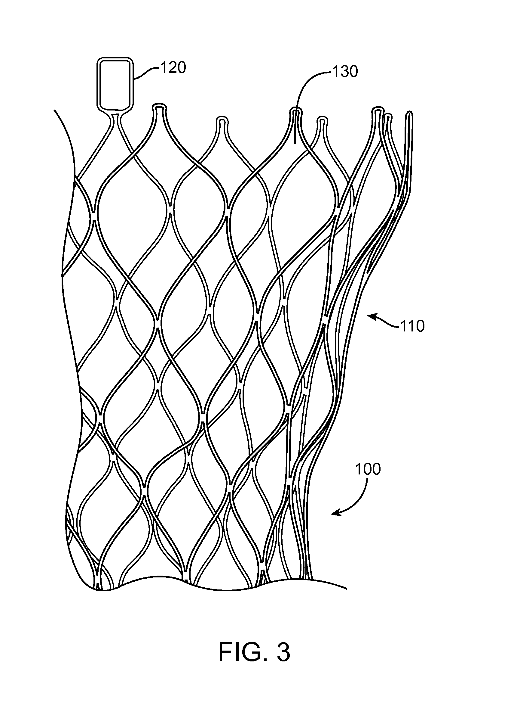
[0009]Provided herein are valve prostheses that generally include a self-expanding frame, where the valve prosthesis is sutured to the self-expanding frame. Such configurations achieve numerous goals. For example, such configurations can: prevent the native leaflets from obstructing flow through the left ventricular outflow tr

Problems solved by technology

Such procedures are traumatic to the patient, require a long recovery time, and can result in life threatening complications.
Therefore, many patients requiring cardiac valve replacement are deemed to pose too high a risk for open heart surgery due to age, health,

Method used


Image

  • Valve Prosthesis
  • Valve Prosthesis
  • Valve Prosthesis

Examples


Embodiment Construction

[0036]The following detailed description of a valve prosthesis frame and delivery system refers to the accompanying figures that illustrate exemplary embodiments. Other embodiments are possible. Modifications can be made to the embodiments described herein without departing from the spirit and scope of the present invention. Therefore, the following detailed description is not meant to be limiting.

[0037]The present invention is directed to a heart valve prosthesis having a self-expanding frame that supports a valve body. The valve prosthesis can be delivered percutaneously to the heart to replace the function of a native valve. For example, the valve prosthesis can replace a bicuspid or a tricuspid valve such as the aortic, mitral, pulmonary, or tricuspid heart valve.

[0038]In one aspect of the invention, the valve body comprises three leaflets that are fastened together at enlarged lateral end regions to form commissural joints, with the unattached edges forming the coaptation edges...


PUM

PropertyMeasurementUnit
Angleaaaaaaaaaa
Angleaaaaaaaaaa
Diameteraaaaaaaaaa

Abstract

A heart valve prosthesis and delivery systems are provided for replacing a cardiac valve. The heart valve prosthesis includes a self-expanding frame includes a portion having a crimp that provides additional flexibility to the self-expanding frame in the collapsed configuration.

Description

BACKGROUND OF THE INVENTION[0001]1. Field of the Invention[0002]The present invention is related to an artificial heart valve frame. More specifically, the present invention is directed to an artificial valve prosthesis.[0003]2. Background Art[0004]Cardiac valves exhibit two types of pathologies: regurgitation and stenosis. Regurgitation is the more common of the two defects. Either defect can be treated by a surgical repair. Under certain conditions, however, the cardiac valve must be replaced. Standard approaches to valve replacement require cutting open the patient's chest and heart to access the native valve. Such procedures are traumatic to the patient, require a long recovery time, and can result in life threatening complications. Therefore, many patients requiring cardiac valve replacement are deemed to pose too high a risk for open heart surgery due to age, health, or a variety of other factors. These patient risks associated with heart valve replacement are lessened by the ...

Claims


Application Information

Patent Timeline
IPC IPC(8): A61F2/24B21D51/16
CPCA61F2/2418A61F2/2436A61F2230/0013A61F2230/0078A61F2230/008A61F2250/0039Y10T29/49405A61F2/2427A61F2/2433
Inventor DWORK, JOSHUA
Owner MEDTRONIC INC
Why Eureka
Try Eureka