Electronic readout for piston-type differential pressure gauge

a differential pressure gauge and electronic reading technology, applied in the direction of fluid pressure measurement by mechanical elements, fluid pressure measurement using pistons, instruments, etc., can solve the problems of filter element clogging or clogging, fluid that escapes through the filter may increase to an unacceptable or hazardous level, and loses its effectiveness.

Inactive Publication Date: 2012-02-16
PARKER HANNIFIN CORP
View PDF17 Cites 25 Cited by
  • Summary
  • Abstract
  • Description
  • Claims
  • Application Information

AI Technical Summary

Benefits of technology

[0010]In some embodiments, a piston-type differential pressure gauge configured to provide electronic output comprises a housing, piston, backing spring, high and low pressure inlets, and a linear potentiometer. The piston includes a magnetic portion and is slidably disposed within the housing and separates the housing into a high pressure side and a low pressure side. The backing spring is disposed within the housing and operable to engage the piston on the low pressure side. A high pressure inlet is coupled to the high pressure side of the housing and a low pressure inlet is coupled to the low pressure side of the housing. The linear potentiometer is coupled to the housing and is operable to sense a position of the

Problems solved by technology

As these particles accumulate, the filter element becomes plugged or clogged and loses its effectiveness.
As a result, an amount of particulate matter in the fluid that escapes through the filter may increase to an unacceptable or hazardous level and may damage the equipment using the fluid or may allow an unacceptable level of contaminants to escape into the atmosphere.
However, piston-type differential pressure gauges have a very large existing user base for monitoring filter differential pressure, particularly for aviation fuel filter uses, and these gauges do not provide electronic output for use with electronic data acquisition systems.

Method used


Image

  • Electronic readout for piston-type differential pressure gauge
  • Electronic readout for piston-type differential pressure gauge
  • Electronic readout for piston-type differential pressure gauge

Examples


Embodiment Construction

[0017]The following description of technology is merely exemplary in nature of the subject matter, manufacture and use of one or more inventions, and is not intended to limit the scope, application, or uses of any specific invention claimed in this application or in such other applications as may be filed claiming priority to this application, or patents issuing therefrom. In respect of the methods disclosed, the steps presented are exemplary in nature, and thus, the order of the steps is not necessary or critical.

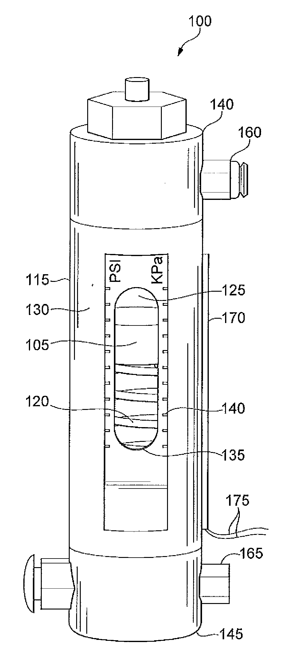
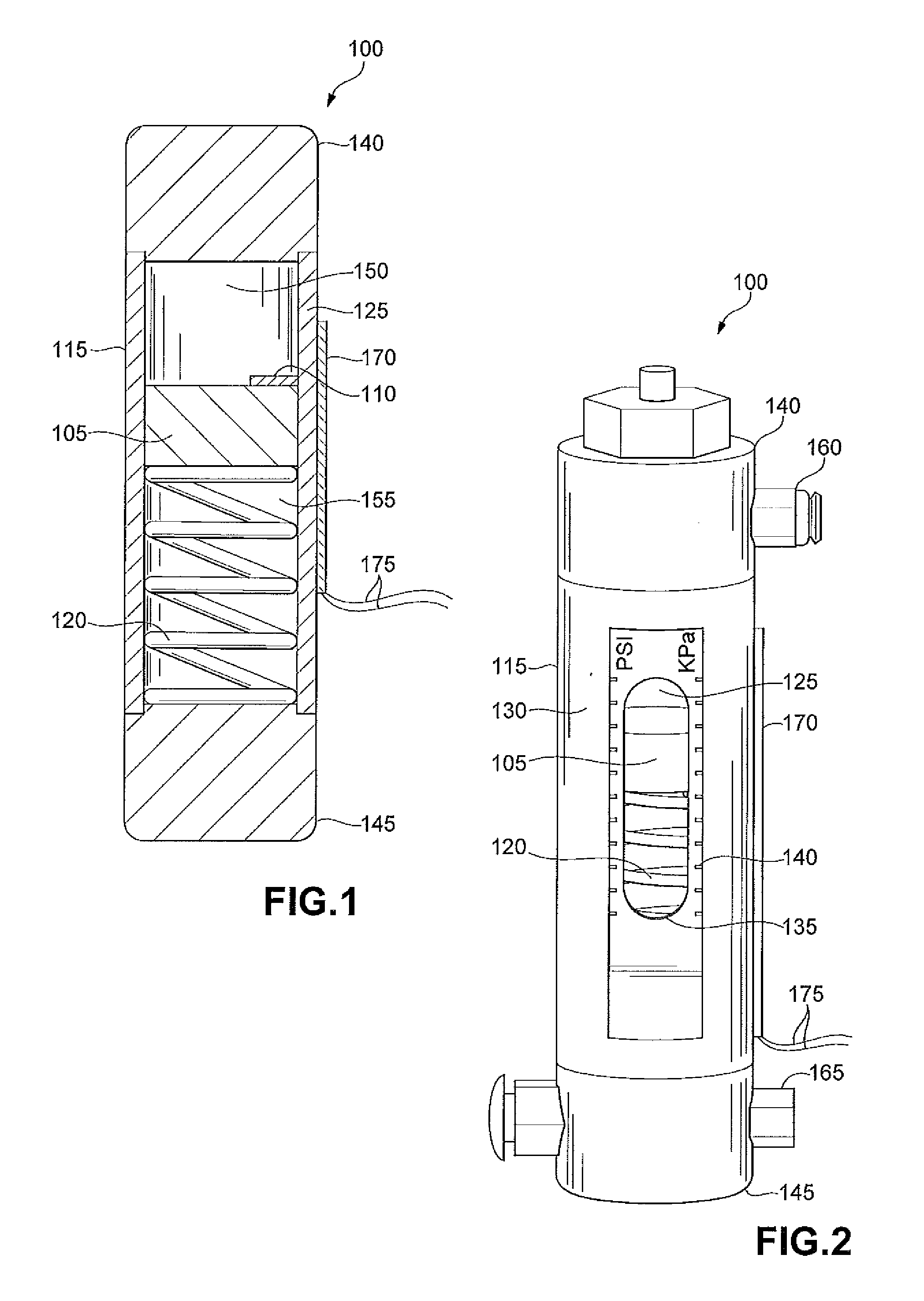
[0018]The present technology relates to devices and methods for providing an electronic output for piston-type differential pressure gauges that can be used to monitor filter differential pressures, for example, such as those used in aviation fuel filters. Incorporating an electronic output for the piston-type device provides an effective upgrade for this established class of gauges. The present technology includes new piston-type differential pressure gauges providing ele...


PUM


Abstract

A piston-type differential pressure gauge provides an electronic output for remote monitoring. A linear potentiometer, in communication with a magnetic portion of the piston of the gauge, tracks the location of the piston. Resistance change in the potentiometer can be used by an electronic circuit to provide the electronic output of the differential pressure remotely to a data acquisition system or control electronics.

Description

CROSS-REFERENCE TO RELATED APPLICATION[0001]The present application claims the benefit of U.S. Provisional Patent Application Ser. No. 61 / 372,896 filed on Aug. 12, 2010, hereby incorporated herein by reference in its entirety.FIELD OF THE INVENTION[0002]The present technology relates generally to a piston-type differential pressure gauge, with attached linear potentiometer, for electronic output of differential pressure.BACKGROUND OF THE INVENTION[0003]This section provides background information related to the present disclosure which is not necessarily prior art.[0004]Filters are commonly used in various applications to ensure that a liquid meets a certain standard of purity or cleanliness. For example, various fluids such as gasoline and hydraulic fluids can be filtered to ensure that there are no particles in the fluid that might damage an engine or a pump. In some cases, various gases such as an exhaust gas can be filtered to minimize the pollution generated by an engine. Appli...

Claims


Application Information

Patent Timeline
IPC IPC(8): G01L7/16
CPCG01L9/0089
Inventor SPRENGER, GREGORY S.GISH, MICHAEL J.GIBSON, JEFF
Owner PARKER HANNIFIN CORP
Why Eureka
Try Eureka