
Apparatus and method for heating heat-shrinkable pipe sleeves

a technology of applicator and heat shrinking sleeve, which is applied in the direction of lighting and heating apparatus, mechanical apparatus, furniture, etc., can solve the problems of unnecessary heating devices spanning a long distance over the length of the applicator, and possibly waste of space and energy, and achieve the effect of quick and easy replacemen

Inactive Publication Date: 2012-02-16
SAIPEM SPA
View PDF8 Cites 14 Cited by
  • Summary
  • Abstract
  • Description
  • Claims
  • Application Information

AI Technical Summary

Benefits of technology

[0013]Providing, first, second, and third heater devices along the length of the sleeve (along the axial direction) enables the heat-delivery apparatus to generate heat to different regions of the sleeve, in a controlled manner, without requiring axial movement of heater devices during the heating time period. The time needed to heat-shrink a sleeve onto the pipe may therefore be reduced. Individually controlling two or more of the heater devices when applying heat to the heat-shrinkable sleeve may allow better control of the heat-shrinking process, for example, ensuring even heating and / or causing progressive heating / shrinking along at least a part of the length of the sleeve.
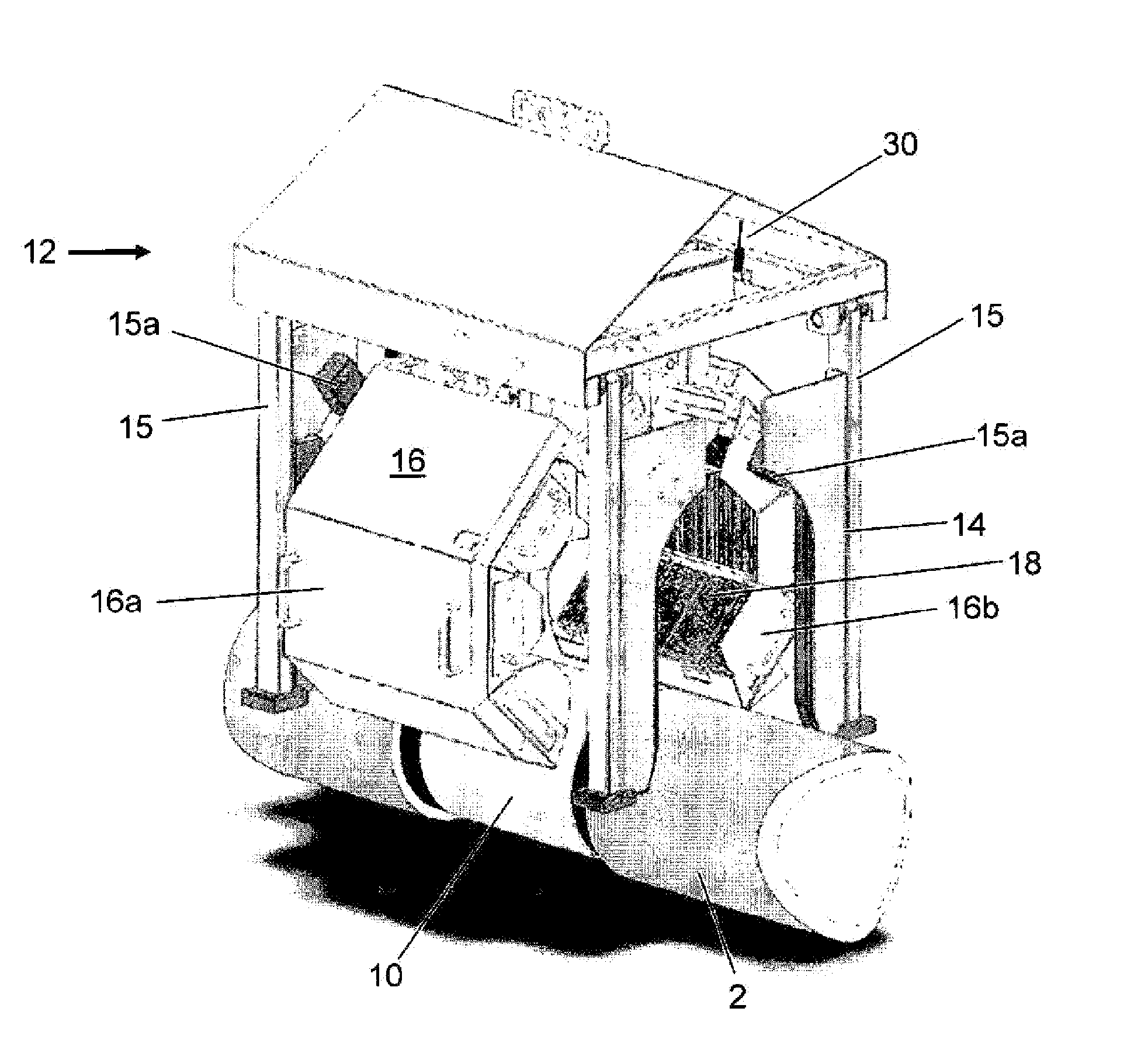
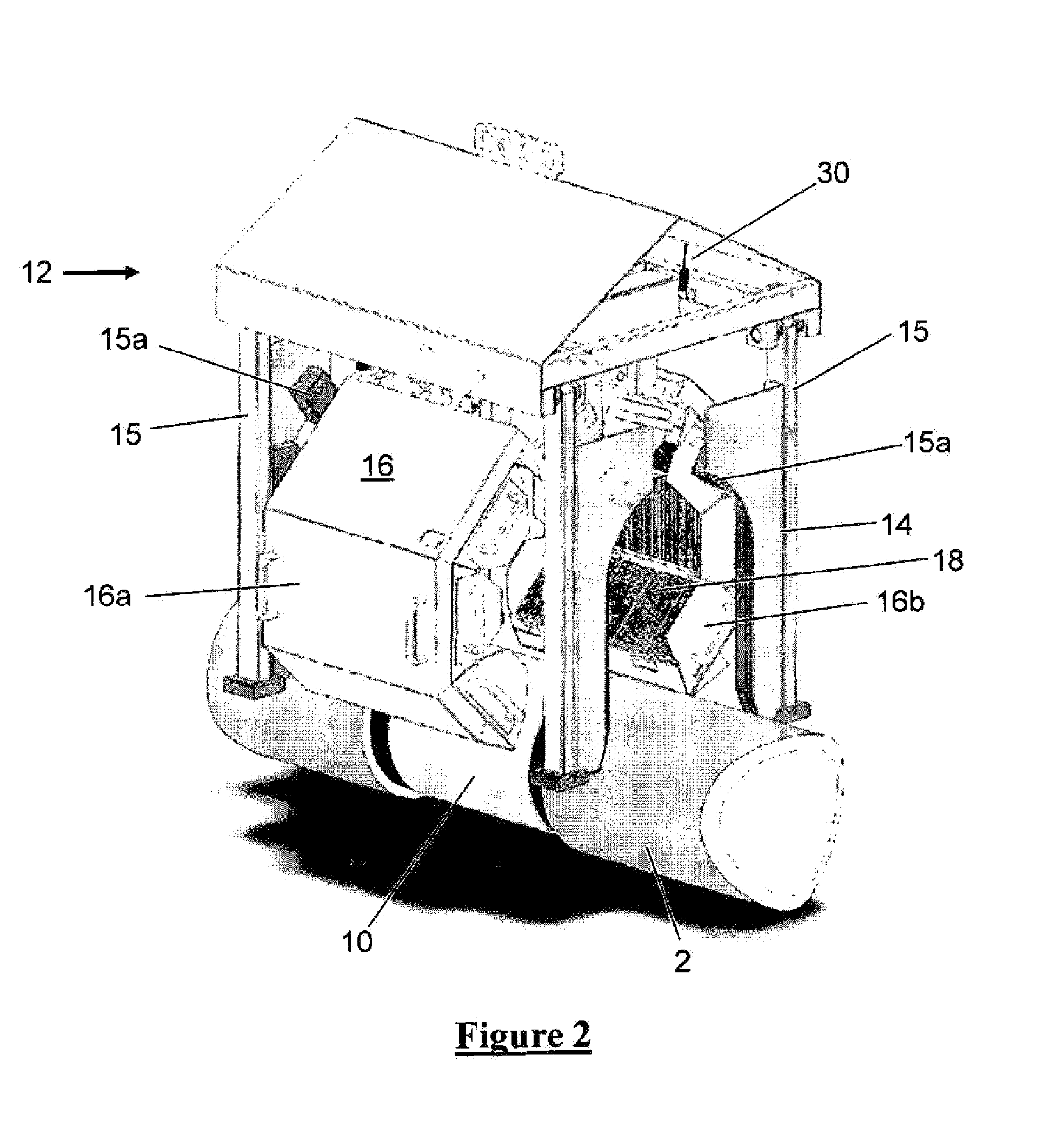
[0015]The method of the invention may be performed in such a manner as to generate heat to the whole of the heat-shrinkable sleeve without moving the heat-delivery apparatus along the length of the sleeve. The method may for example include maintaining the heater devices in fixed position relative to the pipe during a heating time period (for example, a time period covering the time in which all heat required to shrink the sleeve is applied). Not requiring axial movement during heating of the sleeve may further increase the speed at which a sleeve may be shrunk onto the pipe. For example, there may be times at which a plurality of the heater devices are generating heat to the sleeve, such that the majority of, and possibly substantially all of, the external surface of the sleeve is heated at a given instant in time. The distance which the active heating parts of the heating devices span, along the length of the axis of the sleeve, may be greater than the length (i.e. the dimension along the length of the axis) of the sleeve. The length of the span of the heating devices may be slightly longer than the sleeve so as to ensure effective heat treatment of the sleeve at its lateral edges. Of course, arranging the apparatus such that the heating devices span a distance much longer than the length of the sleeve is unnecessary and possibly wasteful of space and energy. The method may include heat-shielding the pipe, or its coating if such coating is present, either side of the sleeve to protect those areas of the pipe from heating by the heater devices in the region of the ends of the sleeve.
[0019]The method may include causing the first heater device to heat the sleeve during said heating time period at a first power level and causing the second heater device to heat the sleeve during said heating time period at a second power lower level, the second power level being higher, for example more than 50% higher, than the first power level. The first and second power levels may be measured by means of measuring the thermal power per unit area delivered to an area of 4 cm2 at a distance of 80 mm away from the centre of the heating element of the heater device. Areas of the sleeve may for example be preheated at a lower power level whilst other areas of the sleeve are being heated at a higher power level. This preheating may be followed by subsequently heating the same area of the sleeve at a higher power level. The preheating may be such that the sleeve does not shrink significantly, but does raise the temperature of the sleeve to just below the temperature at which shrinking occurs. Such a preheating step may allow progressive shrinking of the sleeve in a time-efficient manner.
[0038]The heating elements of each of said at least three heater devices may be in the form of infrared heaters. The heating elements of each of said at least three heater devices may be in the form of panel heaters. Each panel preferably has a flat heating face. The flat faces of the heater panels may be arranged circumferentially and symmetrically around the axis of apparatus to form the general shape of a regular polygon. Each panel may for example define one side of the polygon. Alternatively, each side of the polygon may be defined by a plurality of panels. The apparatus may include a heater-mounting structure associated with each heater element. Each heater element may include a power connector connected to a corresponding power connector of the heater-mounting structure. Each heating element may be removably mounted on the heater-mounting structure. Thus, a defective heating element may be quickly and easily replaced. The means providing the electrical connection between the heating element and the heater-mounting structure may assist in providing the mounting of the heating element on the heater-mounting structure.

Problems solved by technology

Of course, arranging the apparatus such that the heating devices span a distance much longer than the length of the sleeve is unnecessary and possibly wasteful of space and energy.

Method used


Image

  • Apparatus and method for heating heat-shrinkable pipe sleeves
  • Apparatus and method for heating heat-shrinkable pipe sleeves
  • Apparatus and method for heating heat-shrinkable pipe sleeves

Examples


Embodiment Construction

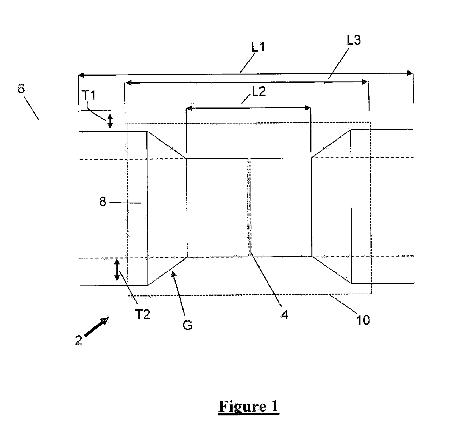
[0050]FIG. 1 shows in cross-section a schematic view of a coated pipeline 2 in the region of a welded joint 4. The pipeline is coated with concrete 6 along its length, but in the region of the joint 4 there is a cut-away portion of a length L1 of about 750 mm where the concrete is absent. The concrete coating 6 has a thickness T1 of about 40 mm. The pipe, being of steel, has a corrosion resistant plastic coating 8 having a thickness T2 of about 2.5 mm. This coating 8 is also cut away to reveal a bare field joint having a length L2 of about 350 mm, in which the uncoated steel pipe is exposed. The external diameter of the uncoated (bare) pipe is about 450 mm. The length of the pipe section being added to the pipeline is about 12 m (40 feet). The plastic pipe coating 8 gradually reduces in thickness from 2.5 mm to 0 mm by means of a gradient G of about 15 to 20 degrees (the scale in FIG. 1 is exaggerated for the sake of illustrating the geometry of the component parts of the pipe in th...


PUM

PropertyMeasurementUnit
Temperatureaaaaaaaaaa
Lengthaaaaaaaaaa
Timeaaaaaaaaaa

Abstract

The present invention provides a method of applying a heat-shrinkable sleeve to a portion of a pipe, the method including the following steps:providing a pipe,arranging a heat-shrinkable sleeve around a portion of the pipe,arranging a heat-delivery apparatus around the pipe in the region of the sleeve, the heat-delivery apparatus including at least three heater devices arranged at different positions along the axis of the pipe, such thata first heater device is positioned closer to the centre of the sleeve, in the axial direction, than second and third heater devices,the second heater device is positioned in the region of a first end of the sleeve, and the third heater device is positioned in the region of a second end of the sleeve opposite to the first end, andindividually controlling each of the first, second and third heater devices to apply heat to the heat-shrinkable sleevewherein each heater device is in the form of an infrared heater device.

Description

BACKGROUND OF THE INVENTION[0001]The present invention concerns an apparatus and method for heating a heat-shrinkable sleeve on a pipe. More particularly, but not exclusively, this invention concerns a method of applying a heat-shrinkable sleeve to a portion of a pipe and a heat-delivery apparatus for heating a heat-shrinkable sleeve around a portion of a pipe.[0002]Pipelines for transportation of hydrocarbons, such as gas or oil pipelines, typically comprise sections of pipe welded together. Each section of pipe may include one or more outer coatings including for example one or more of a corrosion resistant coating, a plastic coating, and a concrete coating. To allow the ends of two sections of pipe to be welded together, the pipe coating at each end includes a cut-back, exposing the metal pipe ends to be welded together. The exposed pipe-ends once welded together may be protected by means of arranging a heat-shrinkable sleeve over them and then attaching the sleeve to the exposed...

Claims


Application Information

Patent Timeline
IPC IPC(8): B32B37/04F27D11/00
CPCB29C61/00B29C63/0069F16L58/181B29C2035/0822F16L13/0272B29C63/42
Inventor NARDO, MARCO
Owner SAIPEM SPA
Learn More