Connector arrangement for a fluid system

a fluid system and connection arrangement technology, applied in the direction of pipes, mechanical equipment, machines/engines, etc., can solve the problems of severe engine damage, affecting the sealing effect, etc., and achieve the effect of avoiding the risk of severe engine damage by contaminated oil and preventing leakage through the apertur

Inactive Publication Date: 2012-02-16
DELPHI INT OPERATIONS LUXEMBOURG S A R L
View PDF6 Cites 12 Cited by
  • Summary
  • Abstract
  • Description
  • Claims
  • Application Information

AI Technical Summary

Benefits of technology

[0014]The nut may be cup-shaped so as to define a side wall carrying an internal screw thread which is engageable with a complementary screw thread provided on the inlet of the first component to secure the nut thereon. In order to prevent leakage through the aperture, the pipe may be shaped to engage the aperture to create a seal.
[0015]The invention provides guards against potential leakages that could occur at the link between the injectors and high pressure pipe work since any leaked fuel is routed away from critical areas and into a backleak passage provided in the injector, the backleak passage serving to convey leaked fuel from clearances and valve arrangements within the injector to a low pressure drain. Therefore, the risk of severe engine damage by contaminated oil is avoided.

Problems solved by technology

A problem exists in the above arrangement in that the effectiveness of the seal may be compromised.
If the injector is installed in such a manner that the inlet end 10 of the injector 2 is housed within a cam cover of an engine, then there exists the potential of engine oil becoming contaminated by fuel leading to severe engine damage.

Method used


Image

  • Connector arrangement for a fluid system
  • Connector arrangement for a fluid system
  • Connector arrangement for a fluid system

Examples


Embodiment Construction

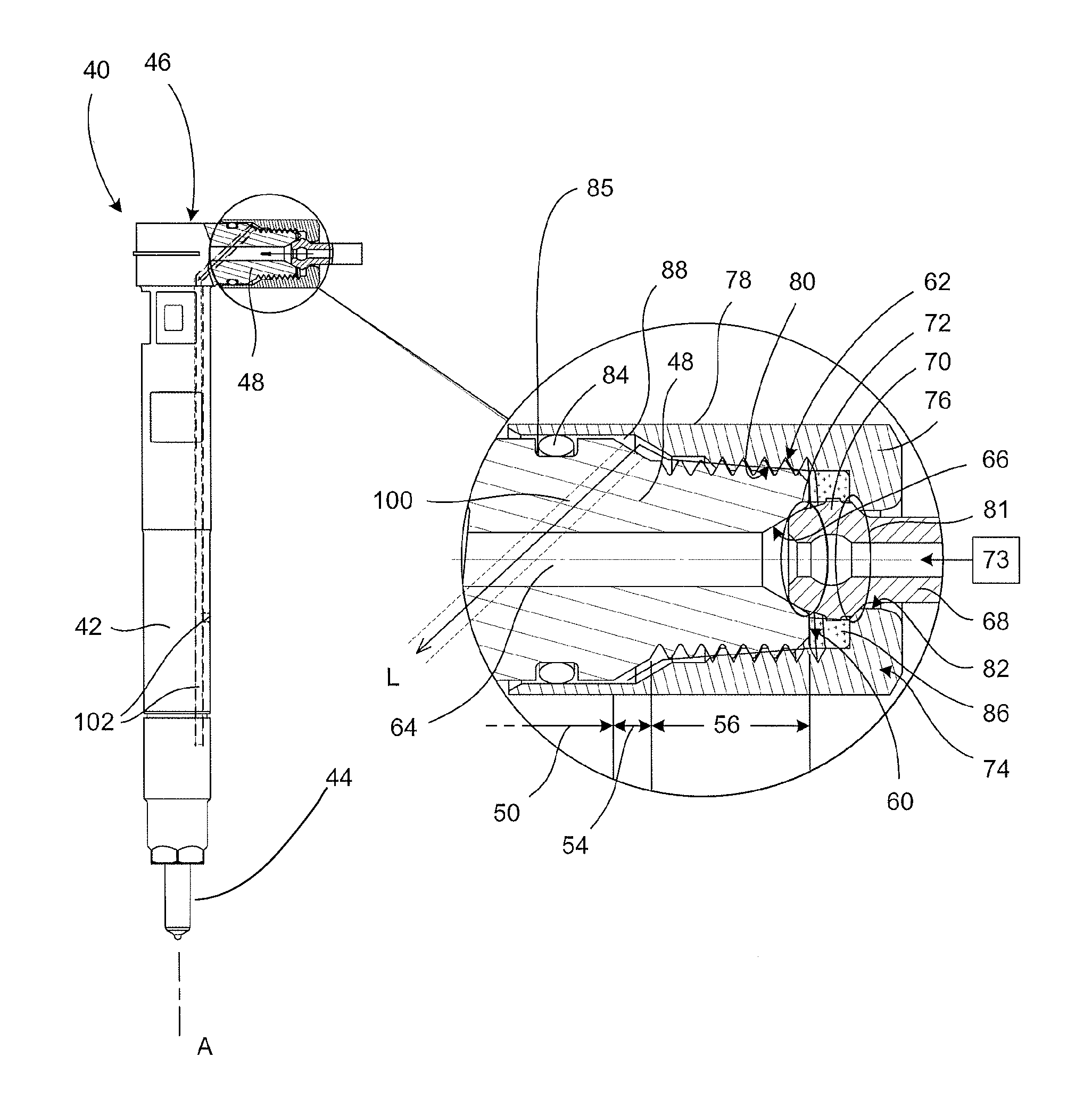
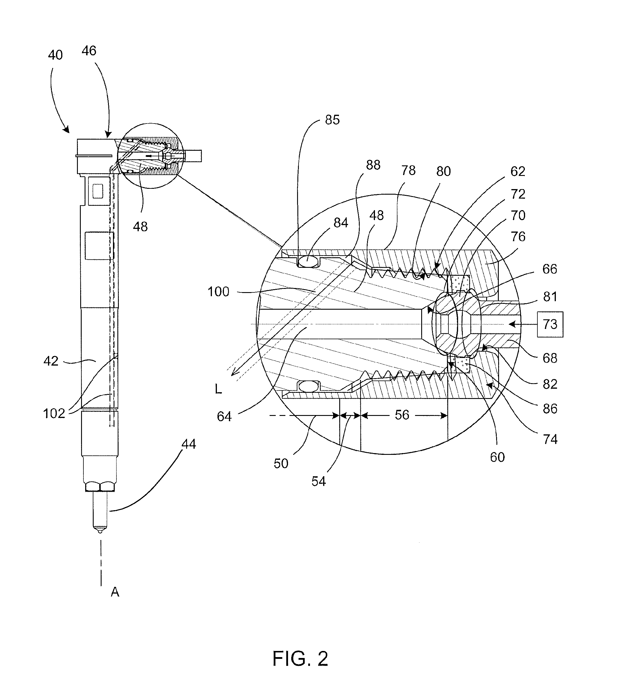
[0017]Referring to FIG. 2, a fuel injector 40 is shown in general outline and includes an elongate injector body 42 that is generally cylindrical in form. The injector body 42 includes a fuel injection nozzle 44 at its lower end (in the orientation shown in FIG. 2) and, at its upper end, the injector body 42 includes a fuel connector or ‘inlet’46 in the form of a transverse projection 48 that extends at right angles to the longitudinal axis ‘A’ of the injector body 42.

[0018]The projection 48 has a stepped outer profile and as such includes a first region 50 which is generally cylindrical and extends a short way from the injector body 42 before tapering sharply to define a transition region 54. A second region 56 extends from the transition region 54 and defines a flat end face 60 of the projection 48. The second region 56 defines an external screw thread 62 on its outer surface.

[0019]The fuel inlet 46 further includes a fuel inlet passage 64 defined by a cross drilling that extends ...


PUM


Abstract

A connector arrangement for a fluid system includes a fuel injector that defines a first fluid passage having a connector, a pipe that is engageable with the connector of the first fluid passage, preferably to form a high pressure seal, and a nut arranged to connect the pipe to the connector of the first fluid passage. A chamber is defined between the nut and the fuel injector, such chamber serving to collect leaked fluid from the first fluid passage. The fuel injector is provided with a second fluid passage having a first end in communication with the chamber and a second end in communication with a low pressure drain such that leaked fuel is provided with a drain path.

Description

TECHNICAL FIELD[0001]The invention relates to a connector arrangement for use in a high pressure fluid system. The invention has particular utility in the field of automotive fuel injection systems in which pipe work for carrying pressurised fluid, for example fuel, is required to be connected to one or more fuel injectors.BACKGROUND OF THE INVENTION[0002]Modern compression-ignition internal combustion engines (hereinafter ‘diesel’ engines) include one or more fuel injectors which are arranged to deliver a shot of fuel at very high pressure into an associated combustion cylinder of the engine. Typically, fuel is distributed to the fuel injectors of the engine from a source of high pressure fuel (for example a high pressure fuel accumulator volume, or ‘common rail’) through a network of high pressure pipes.[0003]FIG. 1 shows a known arrangement in which an injector 2 is supplied with high pressure fuel by a high pressure pipe 4 which defines a fluid passage 5. The injector 2 takes th...

Claims


Application Information

Patent Timeline
Patent Type & Authority Applications(United States)
IPC IPC(8): F02M61/16
CPCF02M55/002F02M55/004F02M55/005F16L19/0283F16L19/028
Inventor LEGRAND, PHILIPPEHAUSMANN, PASCAL
Owner DELPHI INT OPERATIONS LUXEMBOURG S A R L
Why Eureka
Try Eureka