Non-pneumatic survivable tire mounting system for conventional wheels

a technology of conventional wheels and mounting systems, applied in the field of non-pneumatic tires, can solve the problems of affecting the safety of the crew, the pneumatic tires in use on many vehicles may be vulnerable, and the extreme environment of tactical military vehicles,

Active Publication Date: 2012-02-16
THE BOEING CO
View PDF8 Cites 37 Cited by
  • Summary
  • Abstract
  • Description
  • Claims
  • Application Information

AI Technical Summary

Benefits of technology

[0009]Embodiments disclosed herein provide a non-pneumatic tire and wheel assembly incorporating a tire tread and a conventional vehicle wheel with a molded elastomer tire body element received in the tread and having integral wall elements extending radially inward from the tire body element for sealing engagement with the wheel. The tire body element includes multiple concentric layers with alternating spokes.

Problems solved by technology

Tactical military vehicles are subject to extreme environments and the potential for combat damage.
Existing pneumatic tires in use on many vehicles may be vulnerable to blast and fragmentation effects from improvised explosive devices (IED) and other explosive or penetrating threats which render military vehicles inoperable and can leave their crew stranded in harms way.
Additionally, flexing of tire walls in pneumatic tires may create heating that may increase detectable thermal emissions.
Armor shielding provides protection from small arms fire and fragments, but greatly increases vehicle weight, reduces payload, reduces mobility and maneuverability, and reduces vehicle range.
Existing wheel / tire covers are mounted outboard of the pneumatic tire due to the tire wall bulge where they are vulnerable to terrain obstacles and may be damaged or destroyed in the course of rugged terrain operations.
Solid rubber tires provide desired puncture resistance but may be heavy and have excessive rotating inertia for many desired applications.
Wheel / tire combinations created from plastic or composite matrix materials are entering use but may be difficult to fabricate in a manner to be interchangeable with existing pneumatic tire and wheel systems on vehicles.
Non-pneumatic tire systems are not currently mountable to convention vehicle wheels.

Method used


Image

  • Non-pneumatic survivable tire mounting system for conventional wheels
  • Non-pneumatic survivable tire mounting system for conventional wheels
  • Non-pneumatic survivable tire mounting system for conventional wheels

Examples


Embodiment Construction

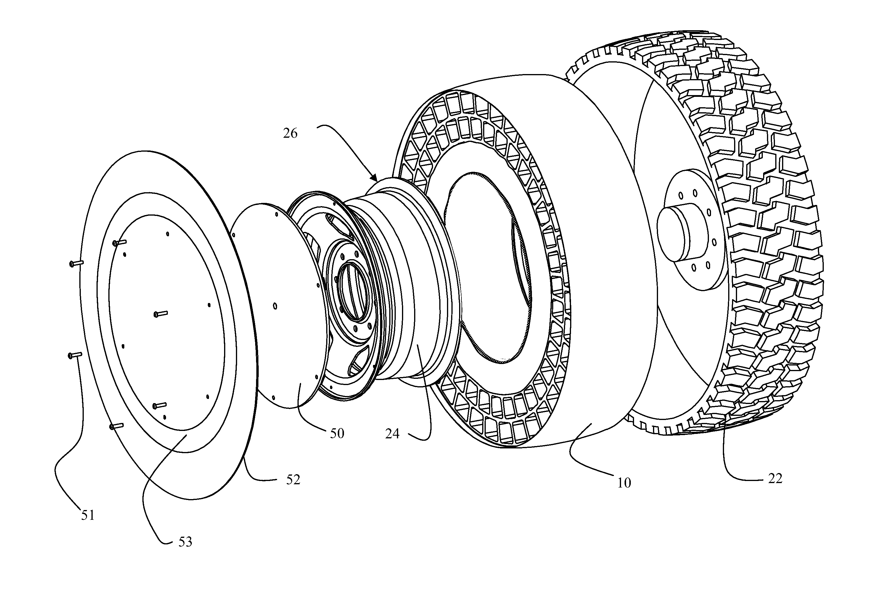
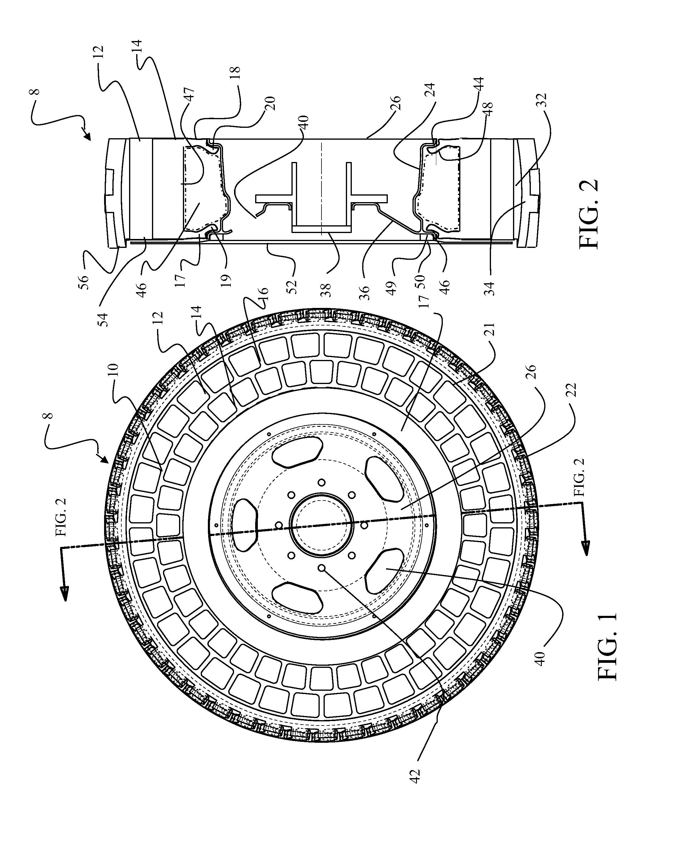
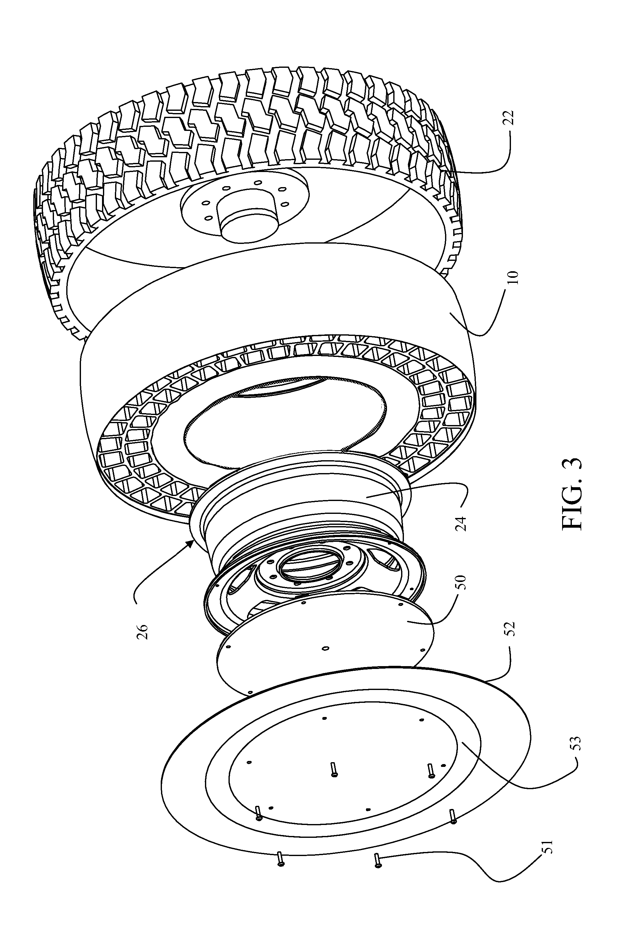
[0018]The embodiments described herein with respect to tactical vehicle use provide a non-pneumatic tire element with hollow spokes that do not block blast pressure, instead allowing the pressure wave to pass-through the tire venting the pressure and reducing likelihood of the tire being blown off the wheel during a blast event. The exemplary urethane cast tire is resistant to small arms fire and is not compromised from minor small arms bullet impacts. The urethane spokes are durable and of sufficient number and strength to provide redundant functionality even after punctures from bullets, nails or other small projectiles. Concentric spoke layers allow a greater number of load paths and flexibility. These redundant load paths provide greater tolerance to IED blast protection and small arms fire. “Run flat or damaged” capability is inherent by eliminating the need for the tire to contain pressurized air.

[0019]The embodiments additionally include a pneumatic interface between the tire...


PUM

PropertyMeasurementUnit
heightaaaaaaaaaa
temperatureaaaaaaaaaa

Abstract

A non-pneumatic tire and wheel assembly incorporates a tire tread and a conventional vehicle wheel with an elastomer tire body element and integral wall elements extending radially inward from the tire body element for sealing engagement with the wheel. The tire body element includes multiple concentric layers with alternating spokes. A bonded multilayer cover may be employed which is received within a recess in an outer surface of the tire body element from the tire tread. An attachment plate is engaged to the cover and attached to the wheel.

Description

REFERENCE TO RELATED APPLICATIONS[0001]This application is co-pending with U.S. patent application Ser. No. ______ entitled NON-PNEUMATIC SURVIVABLE TIRE, COVER AND FABRICATION PROCESSES by Daniel J Perron, Eldon C. Rogers, Darrell M. Storvick, Timothy L. Williams, Dennis Yee and D'Arcy R. Chadwick, attorney docket no. 10-0149, filed substantially concurrently herewith the disclosure of which is incorporated herein by reference as though fully set forth.BACKGROUND INFORMATION[0002]1. Field[0003]Embodiments of the disclosure relate generally to the field of non-pneumatic tires and more particularly to embodiments for a survivable non-pneumatic tire having molded construction with a flexible spoke structure for tactical wheeled vehicle application with an integral pneumatic interface for mounting to conventional wheels[0004]2. Background[0005]Tactical military vehicles are subject to extreme environments and the potential for combat damage. Existing pneumatic tires in use on many vehi...

Claims


Application Information

Patent Timeline
Patent Type & Authority Applications(United States)
IPC IPC(8): B60C7/00B29D30/00B60B7/02
CPCB60C7/18B60C2007/107B29D30/0061B29D30/02Y10T29/49494Y10T152/10297Y10T29/49538B60C7/107
Inventor WILLIAMS, TIMOTHY L.ROGERS, ELDON C.
Owner THE BOEING CO
Why Eureka
Try Eureka