

Rotating electric machine and production method for rotating electric machine
a technology of rotating electric machines and electric motors, applied in the direction of dynamo-electric machines, electrical apparatus, embedding prefabricated windings, etc., can solve problems such as insulation failure, and achieve the effects of reducing the size of the rotating electric machine, ensuring the spatial distance, and reducing the creepage distan
- Summary
- Abstract
- Description
- Claims
- Application Information
AI Technical Summary
Benefits of technology
Problems solved by technology
Method used
Image

Examples
first embodiment
[0025]A rotating electric machine in the first embodiment of the present invention will now be explained in detail with reference to the drawings.
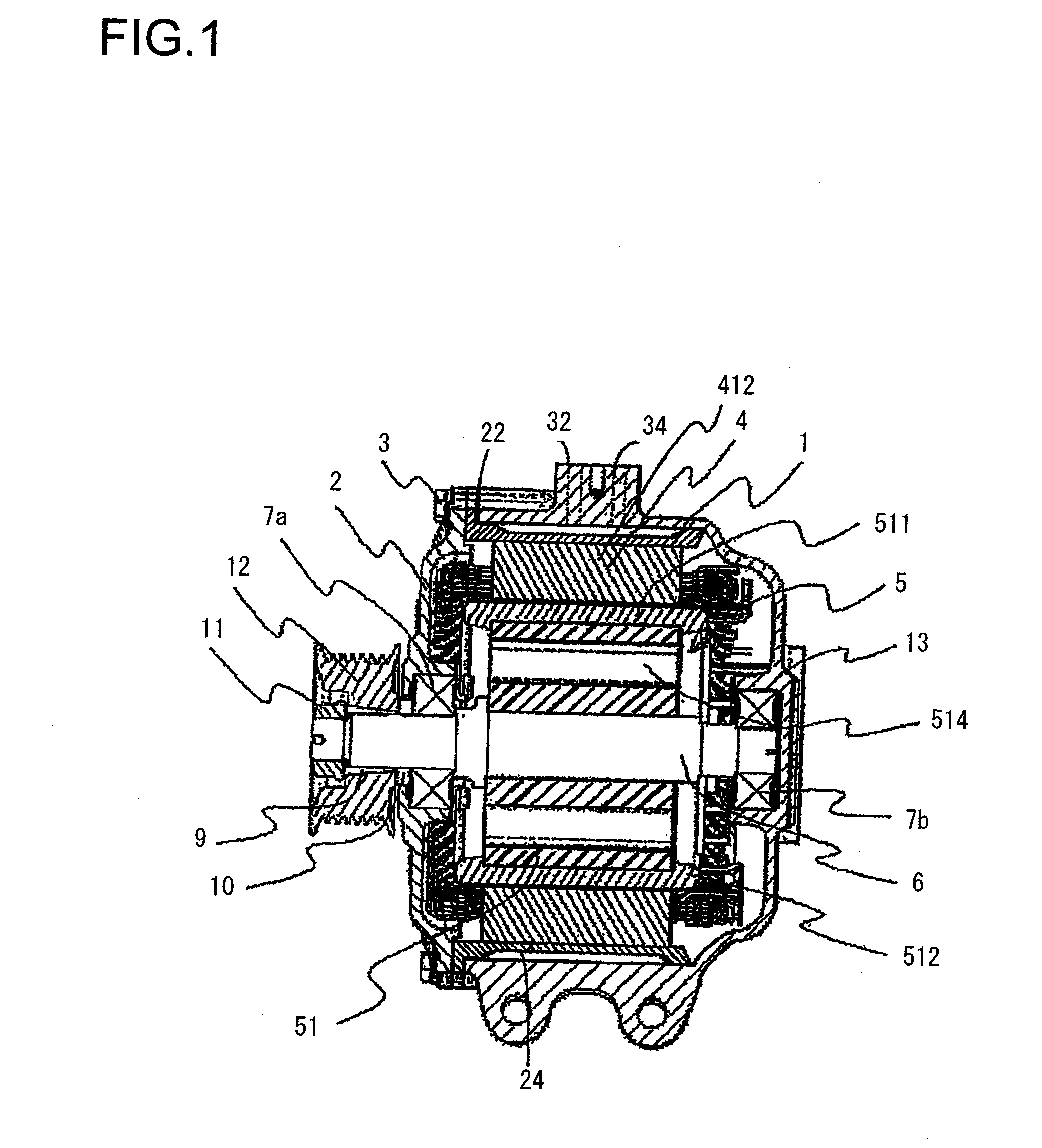
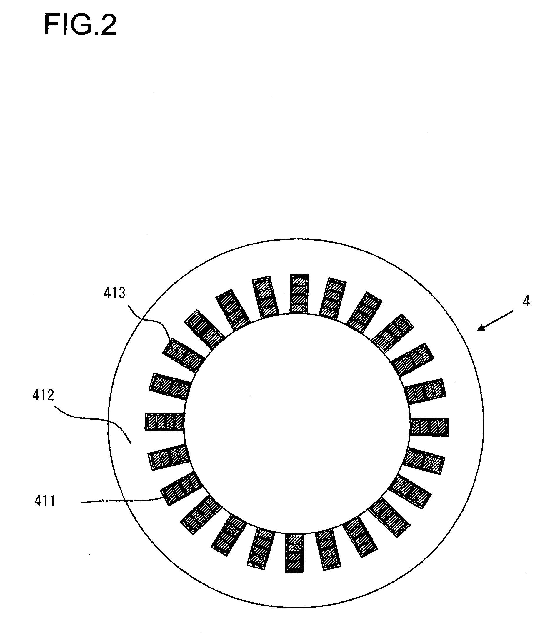
[0026]FIG. 1 is a side sectional view of an induction rotating electric machine in the first embodiment, FIG. 2 is a view showing a cross section of the stator, and FIG. 3 is a perspective view showing a cross section of the rotor. The induction rotating electric machine includes a bottomed cylindrical housing 1 having an opening at one axial end side and a cover 2 sealing the opening end of the housing 1. The housing 1 and the cover 2 are fastened with a plurality of, for instance, six bolts 3. The housing 1 is provided with a water path forming member 22 inside thereof, and a stator 4 is fixed to the inside of the water path forming member 22 by shrink fitting or the like. A flange of the water path forming member 22, shown on the left of the figure, is sandwiched between and fixed to the housing 1 and the cover 2, so that a water path 2...
second embodiment
[0045]The rotating electric machine according to the second embodiment of the present invention will now be explained. The overall structure of the rotating electric machine in the second embodiment is the same as that of the first embodiment described above. The following explanation will mainly focus upon the difference from the first embodiment.
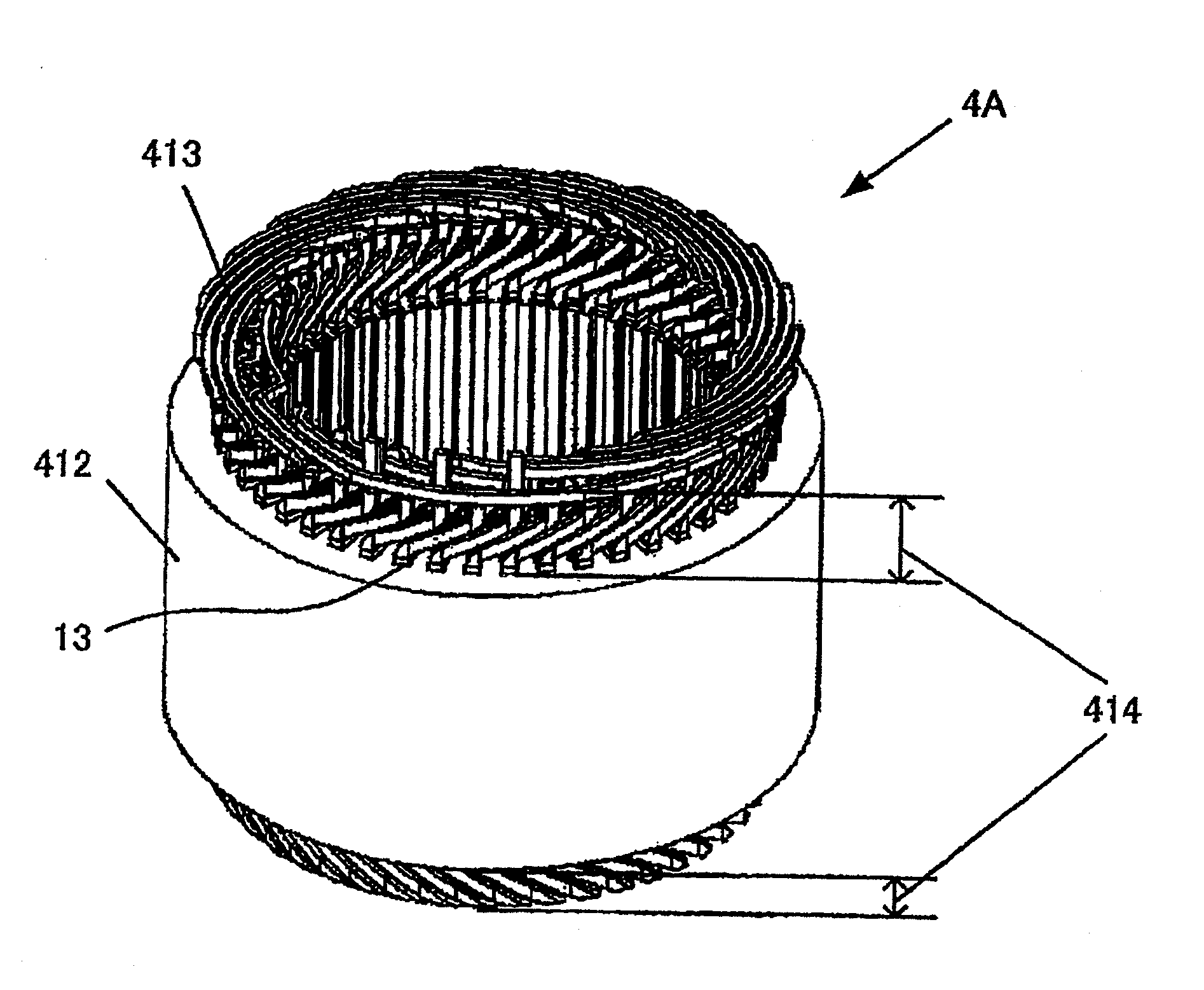
[0046]In the production method for the stator coil 413 in the first embodiment described above, the conductor which constitutes the stator coil 413 is inserted into the slot 411 before the conductor is bent at a predetermined angle so as to form the stator coil 413. However, if the slot 411 of the stator core 412 is a so-called open slot as shown in FIG. 2, a conductor bent in advance at a predetermined angle may be inserted into the slot 411 so as to form the stator coil 413. The production method for the stator coil 413 according to the second embodiment will now be explained in detail.
[0047]At first, as shown in FIG. 10(a), a rectangula...
third embodiment
[0052]The rotating electric machine according to the third embodiment of the present invention will now be explained. The overall structure of the rotating electric machine in the third embodiment is the same as that of the first embodiment described above. The following explanation will mainly focus upon the difference from the first embodiment.
[0053]As described earlier, in a low voltage rotating electric machine of, for example, equal to or less than 600 V, it is necessary to ensure each of the creepage distance and the spatial distance between the stator core 412 and the stator coil 413 to be at least 1.5 mm. However, it may be difficult to ensure each of the creepage distance and the spatial distance to be at least 1.5 mm in a small rotating electric machine for instance. Then, in the third embodiment, even if it is difficult to form the slot groove 415 with the depth and the width of at least 1.5 mm, insulation failure due to insufficient creepage distance and spatial distance...
PUM
| Property | Measurement | Unit |
|---|---|---|
| Electric potential / voltage | aaaaa | aaaaa |
| Width | aaaaa | aaaaa |
| Depth | aaaaa | aaaaa |
Abstract
Description
Claims
Application Information