Controller for a Power Converter and Method of Operating the Same

a power converter and control board technology, applied in the field of power electronics, can solve the problems of process defeating the quasi-resonant switching operation of the power converter, the difficulty of achieving quasi-resonant power converter operation, and the regulation of the output current of the power converter

Active Publication Date: 2012-02-16
POWER SYST TECH
View PDF11 Cites 45 Cited by
  • Summary
  • Abstract
  • Description
  • Claims
  • Application Information

AI Technical Summary

Benefits of technology

[0010]These and other problems are generally solved or circumvented, and technical advantages are generally achieved, by advantageous embodiments of the present invention, including a controller for a power converter and method of operating the same. In one embodiment, the controller includes a peak detector, coupled to a circuit element of the power converter, configured to produce a signal corresponding to a peak current through a circuit element. The controller also includes an adjustable reference circuit responsive to a difference between the signal and a reference signal corresponding to a desired peak current to produce a corrected signal corresponding to the peak current.

Problems solved by technology

With conventional design approaches, however, it is difficult to achieve quasi-resonant power converter operation and, at the same time, regulate an output current of the power converter.
This process may defeat quasi-resonant switching operation of the power converter.
This approach increases power converter cost due to the presence of the optocoupler.
This approach preserves quasi-resonant switching without the need for an optocoupler, but requires a complex calculation in the controller.
If a peak current in a winding of the magnetic circuit element is not limited or otherwise controlled to a constant level, this can have an unwanted effect on output of the power converter (e.g., an output ripple can increase), and a primary-controlled output current limit can exhibit an unwanted level of variation.
The comparator, the control logic and the power switch, however, operate with inherent delays that can be variable as a function of the operating environment and sensed voltages.
Due to these inherent and variable delays, current in the power switch and the magnetic circuit element continues to rise with the result that the peak of the current becomes higher than the desired current limit by a variable amount that is generally dependent on an input voltage to the power converter.
Thus, a peak current limiter that limits a peak current of a power converter that produces a constant level thereof still presents unresolved design challenges.

Method used


Image

  • Controller for a Power Converter and Method of Operating the Same
  • Controller for a Power Converter and Method of Operating the Same
  • Controller for a Power Converter and Method of Operating the Same

Examples


Embodiment Construction

[0023]The making and using of the present exemplary embodiments are discussed in detail below. It should be appreciated, however, that the present invention provides many applicable inventive concepts that can be embodied in a wide variety of specific contexts. The specific embodiments discussed are merely illustrative of specific ways to make and use the invention, and do not limit the scope of the invention.

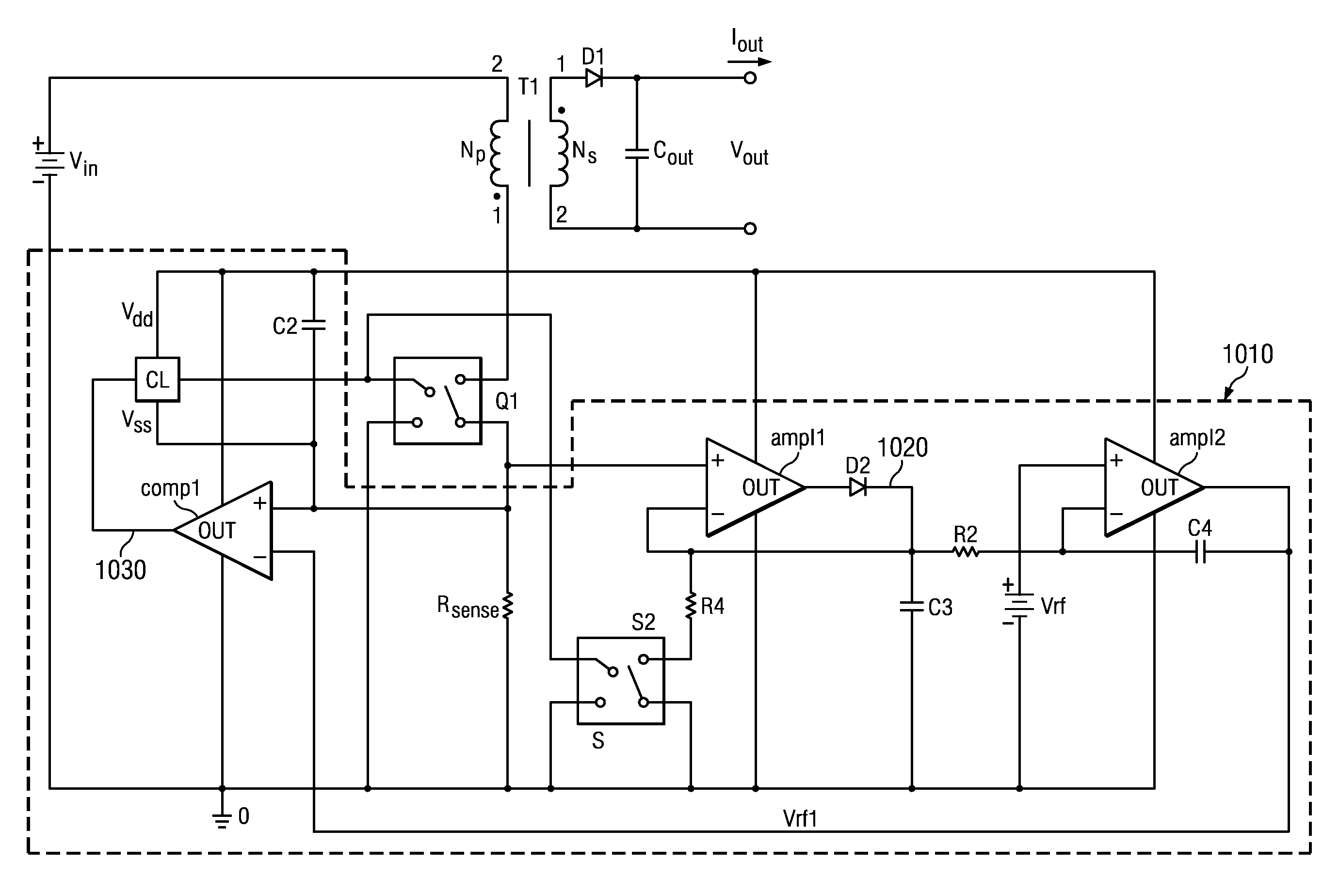
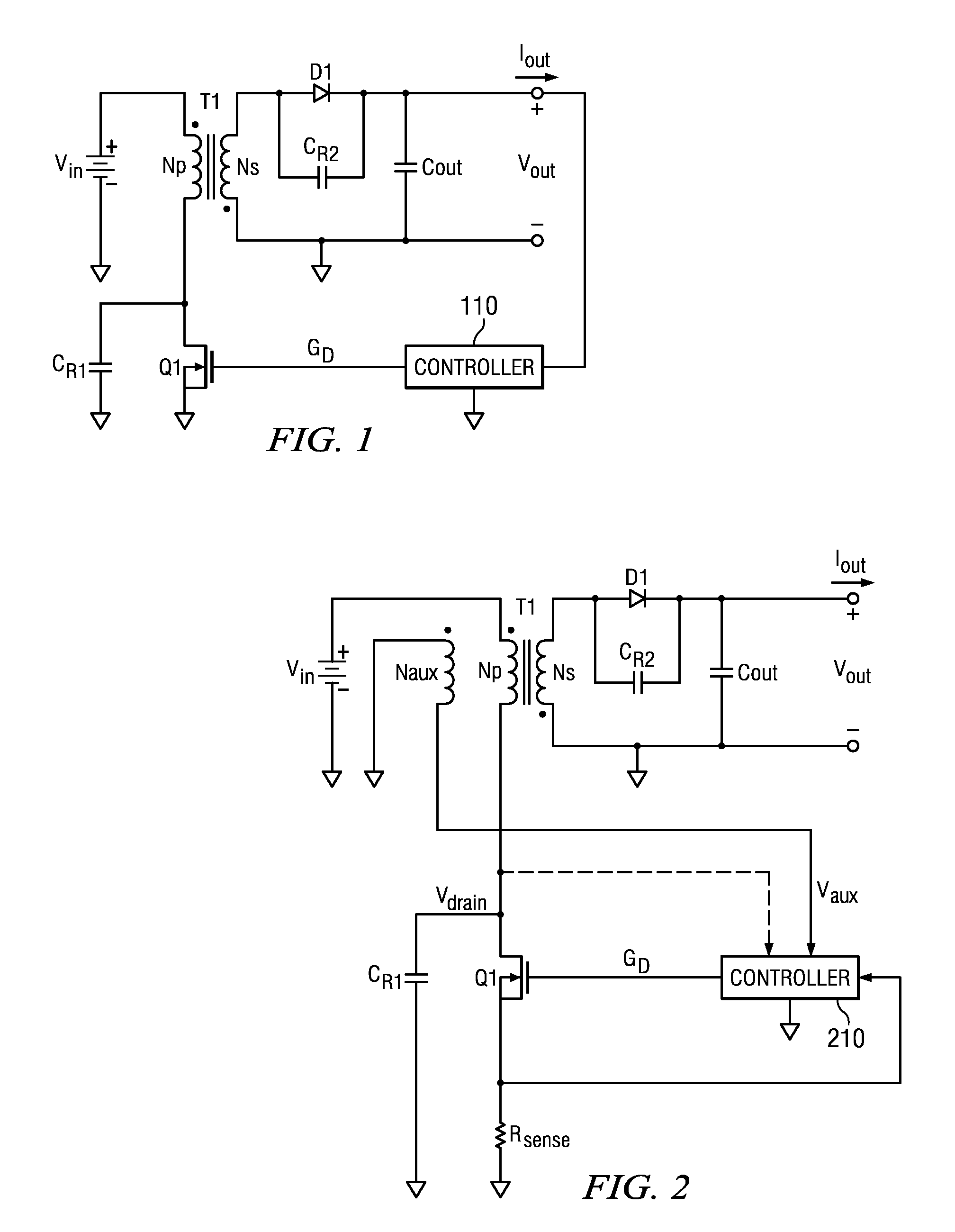
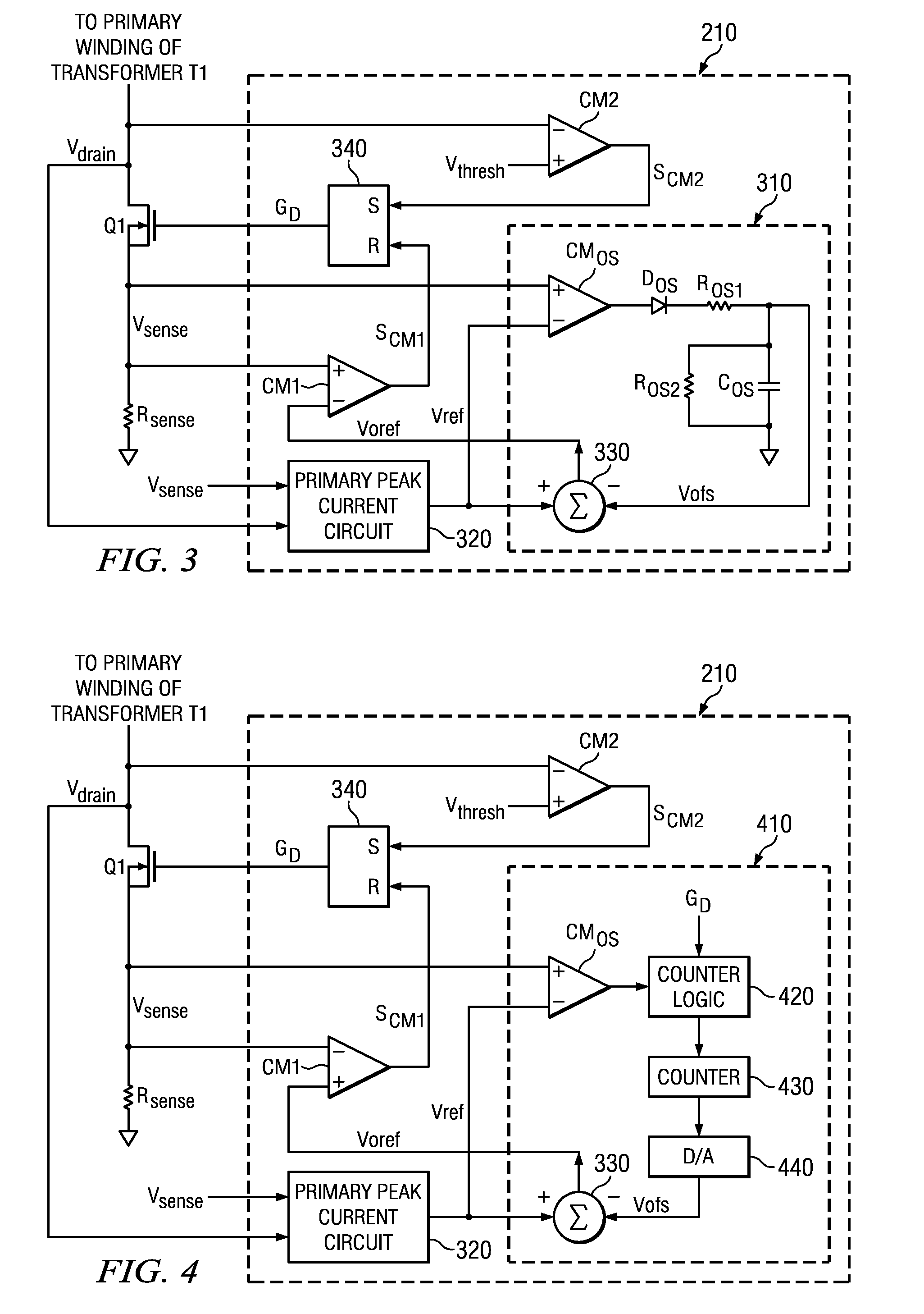
[0024]The present invention will be described with respect to exemplary embodiments in a specific context, namely, a controller for a power converter (e.g., a flyback power converter) including a peak detector coupled to a circuit element (e.g., a power switch) of the power converter configured to produce a signal corresponding to a peak current through the power switch, and an adjustable reference circuit responsive to a difference between the signal and a reference signal corresponding to a desired peak current to produce a corrected signal corresponding to the peak current. ...


PUM


Abstract

A controller for a power converter and method of operating the same. In one embodiment, the controller includes a peak detector, coupled to a circuit element of the power converter, configured to produce a signal corresponding to a peak current through a circuit element. The controller also includes an adjustable reference circuit responsive to a difference between the signal and a reference signal corresponding to a desired peak current to produce a corrected signal corresponding to the peak current.

Description

[0001]This application is a continuation in part of, and claims priority to, U.S. patent application Ser. No. 12 / 692,299, entitled “Controller for a Power Converter and Method of Operating the Same,” filed on Jan. 22, 2010, which is incorporated herein by reference.TECHNICAL FIELD[0002]The present invention is directed, in general, to power electronics and, more specifically, to a controller for a power converter and method of operating the same.BACKGROUND[0003]A switched-mode power converter (also referred to as a “power converter” or “regulator”) is a power supply or power processing circuit that converts an input voltage waveform into a specified output voltage waveform. DC-DC power converters convert a direct current (“dc”) input voltage that may be derived from an alternating current (“ac”) source by rectification into a dc output voltage. Controllers associated with the power converters manage an operation thereof by controlling conduction periods of power switches employed th...

Claims


Application Information

Patent Timeline
Patent Type & Authority Applications(United States)
IPC IPC(8): H02M3/335H02M1/00
CPCH02M3/33507H02M2001/0009Y02B70/1433H02M1/0009Y02B70/10
Inventor BERGHEGGER, RALF SCHROEDER GENANNT
Owner POWER SYST TECH
Why Eureka
Try Eureka