Method of channel management for multiple component carrier in mobile communication system

a mobile communication system and multiple component technology, applied in the field of long-term evolution (lte)advanced systems, can solve the problems of increasing the number of retransmissions, increasing the number of data reception errors of the receiver, and increasing the power consumption

Active Publication Date: 2012-02-16
ELECTRONICS & TELECOMM RES INST
View PDF4 Cites 24 Cited by
  • Summary
  • Abstract
  • Description
  • Claims
  • Application Information

AI Technical Summary

Benefits of technology

[0031]A fourth object of the present invention is to provide a channel management method in a carrier aggregation environment which stably controls a secondary-carrier deactivation procedure to prevent carrier states managed by a base station and a terminal from being inconsistent with each other when a secondary carrier is configured and operated in a multicarrier environment.

Problems solved by technology

The wider a frequency bandwidth for use in communication, the higher power consumption.
If traffic between the base station and the terminal increases and a radio channel state of some CCs becomes bad in a state in which multiple carriers are used, the number of data reception errors of a receiver increases and the number of retransmissions increases.
In particular, if a radio channel state of a CC becomes bad in a structure in which retransmission is performed by only the CC used during initial transmission as in the LTE-Advanced system, there is a problem in that the number of reception errors rapidly increases.
Also, there is a problem in that data transmitted once is retransmitted until reception succeeds during a maximum number of retransmissions, regardless of a radio channel state.
This procedure leads to unnecessary retransmission operations and power consumption of the terminal.
Further, there is a problem in that the waste of radio resources and the degradation of base station performance occur because other terminals may not use resources due to unnecessary retransmission.

Method used


Image

  • Method of channel management for multiple component carrier in mobile communication system
  • Method of channel management for multiple component carrier in mobile communication system
  • Method of channel management for multiple component carrier in mobile communication system

Examples


Embodiment Construction

[0058]While the invention is susceptible to various modifications and alternative forms, specific embodiments thereof are shown by way of example in the drawings and will herein be described in detail.

[0059]It should be understood, however, that there is no intent to limit the invention to the particular forms disclosed, but on the contrary, the invention is to cover all modifications, equivalents, and alternatives falling within the spirit and scope of the invention.

[0060]The terminology used herein is for the purpose of describing particular embodiments only and is not intended to be limiting of the invention. As used herein, the singular forms “a,”“an,” and “the” are intended to include the plural forms as well, unless the context clearly indicates otherwise. It will be further understood that the terms “comprises,”“comprising,”“includes” and / or “including,” when used herein, specify the presence of stated features, integers, steps, operations, elements, and / or components, but do...


PUM


Abstract

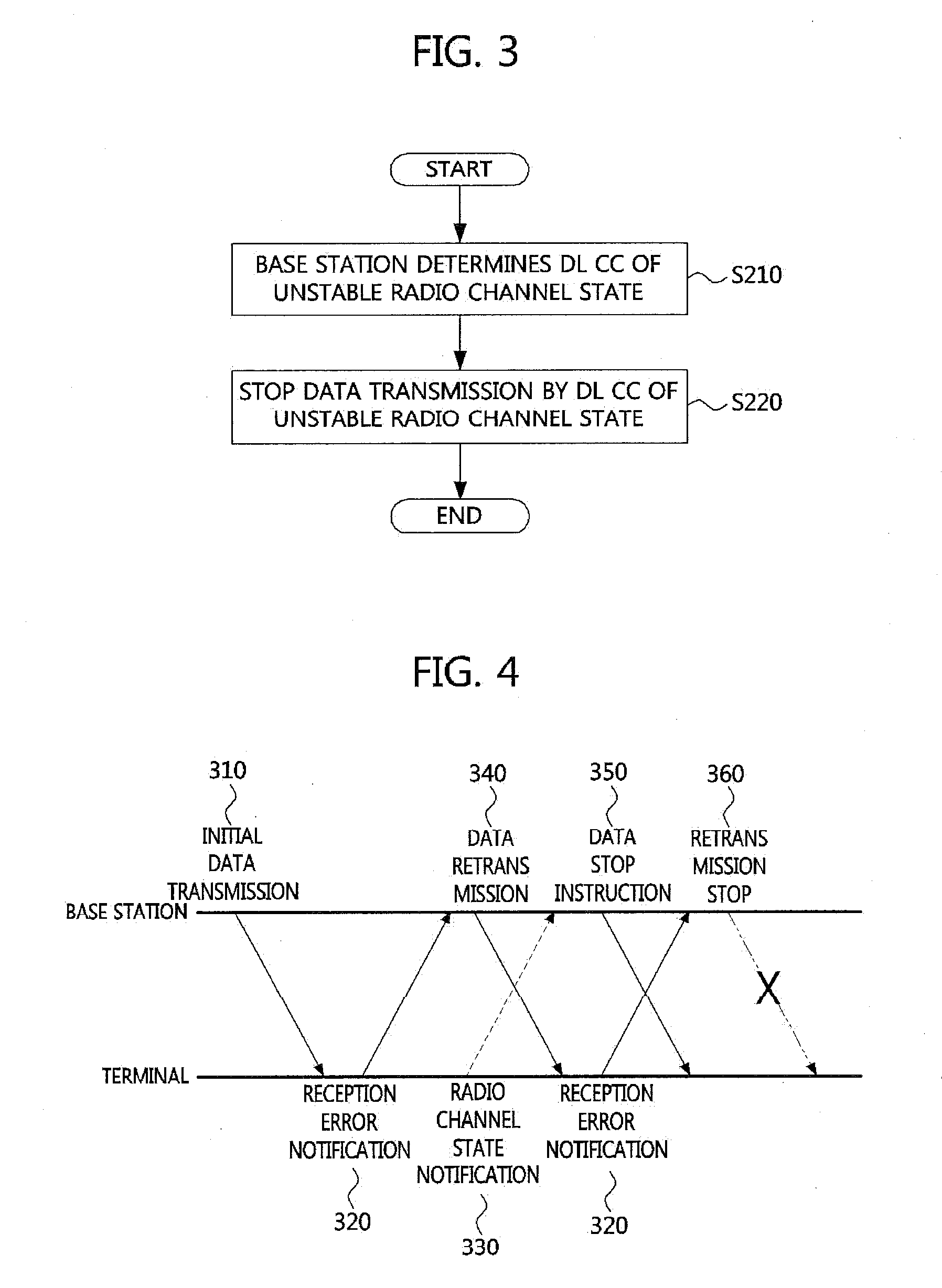
Disclosed are channel management methods in a multicarrier structure in a mobile communication system. Uplink (UL) and downlink (DL) channel management methods in a carrier aggregation environment are used as the channel management methods. In DL, a base station determines a component carrier (CC) of an unstable radio channel state, stops data retransmission by the CC, and notifies a terminal of retransmission stop. In UL, the base station determines a CC of an unstable radio channel state and instructs the terminal to stop data retransmission by the CC, and the terminal stops the data retransmission and initializes a retransmission buffer. Using the channel management methods in the mobile communication system employing the multicarrier structure, an increase in the number of unnecessary retransmissions is prevented, so that unnecessary retransmission and power consumption of the terminal can be reduced and the waste of radio resources and the degradation of base station performance due to unnecessary retransmission can be prevented.

Description

CLAIM FOR PRIORITY[0001]This application claims priority to Korean Patent Application No. 10-2010-0077880 filed on Aug. 12, 2010 and Korean Patent Application No. 10-2010-0110649 filed on Nov. 8, 2010 in the Korean Intellectual Property Office (KIPO), the entire contents of which are hereby incorporated by reference.BACKGROUND[0002]1. Technical Field[0003]Example embodiments of the present invention relate to a Long Term Evolution (LTE)-Advanced system, which is next-generation mobile communication being standardized by the 3rd Generation Partnership Project (3GPP), and more particularly, to a channel management method according to a radio channel state and a channel management method of efficiently performing retransmission (hybrid automatic repeat request (HARQ)) and discontinuous reception (DRX) control of a terminal in a structure in which communication between a base station and the terminal is performed using a plurality of carriers.[0004]2. Related Art[0005]3GPP, which is a m...

Claims


Application Information

Patent Timeline
Patent Type & Authority Applications(United States)
IPC IPC(8): H04W72/04H04W24/00
CPCH04W76/38H04W72/04H04L1/1825H04L1/1854H04L1/1864H04L1/1887H04L1/1896H04L5/001H04L5/0098H04W24/00H04W28/04H04W28/06H04W48/08H04W72/00H04W72/0406H04W72/02H04W52/0216Y02D70/1262Y02D70/24Y02D70/1264Y02D70/00H04W76/28H04L1/0026Y02D30/70H04W72/51H04W72/20
Inventor LEE, KYOUNG SEOKKIM, JAE HEUNGLEE, KOOK JIN
Owner ELECTRONICS & TELECOMM RES INST
Why Eureka
Try Eureka