Integrated Contoured Negative Pressure Bandages

Active Publication Date: 2012-02-16
MEDU SCI
View PDF43 Cites 34 Cited by
  • Summary
  • Abstract
  • Description
  • Claims
  • Application Information

AI Technical Summary

Benefits of technology

[0024]It is yet another advantage of this invention that the time to apply a negative pressure bandage to a wound site is reduced by the utilization of an integrated bandage that allows the wound fluids and exudates to be withdrawn from the bandage to a remote canister.
[0025]It is a further feature of this invention that the contoured negative pressure bandage for application to the heel of a patient's foot is formed with junctions, such as cutouts, to facilitate the sealing of the bandage around the heel.
[0026]It is still a further feature of this invention that the drain tube and associated connector can be oriented diagonally to the primary axes of the bandage to position the connector for attaching the vacuum source to the drain tube in an easily accessible and unobtrusive location.
[0027]It is yet another object of this invention to provide an integrated negative pressure bandage that is durable in construction, inexpensive of manufacture, facile in assemblage, and simple and effective in use.
[0028]It is a further object of this invention to provide a negative pressure bandage that is contoured to fit portions of the human body

Problems solved by technology

Conventional negative pressure bandages are generally large in size and often require the use of complicated equipment such as suction pumps, vacuum pumps and complex electronic controllers to apply a negative pressure within the bandage to draw exudates and fluids away from the wound to a remote collection container.
As a result, negative pressure bandages and r

Method used


Image

  • Integrated Contoured Negative Pressure Bandages
  • Integrated Contoured Negative Pressure Bandages
  • Integrated Contoured Negative Pressure Bandages

Examples


first embodiment

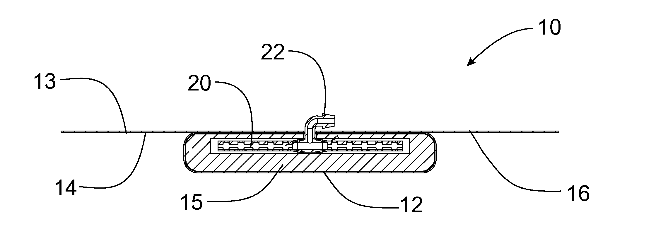
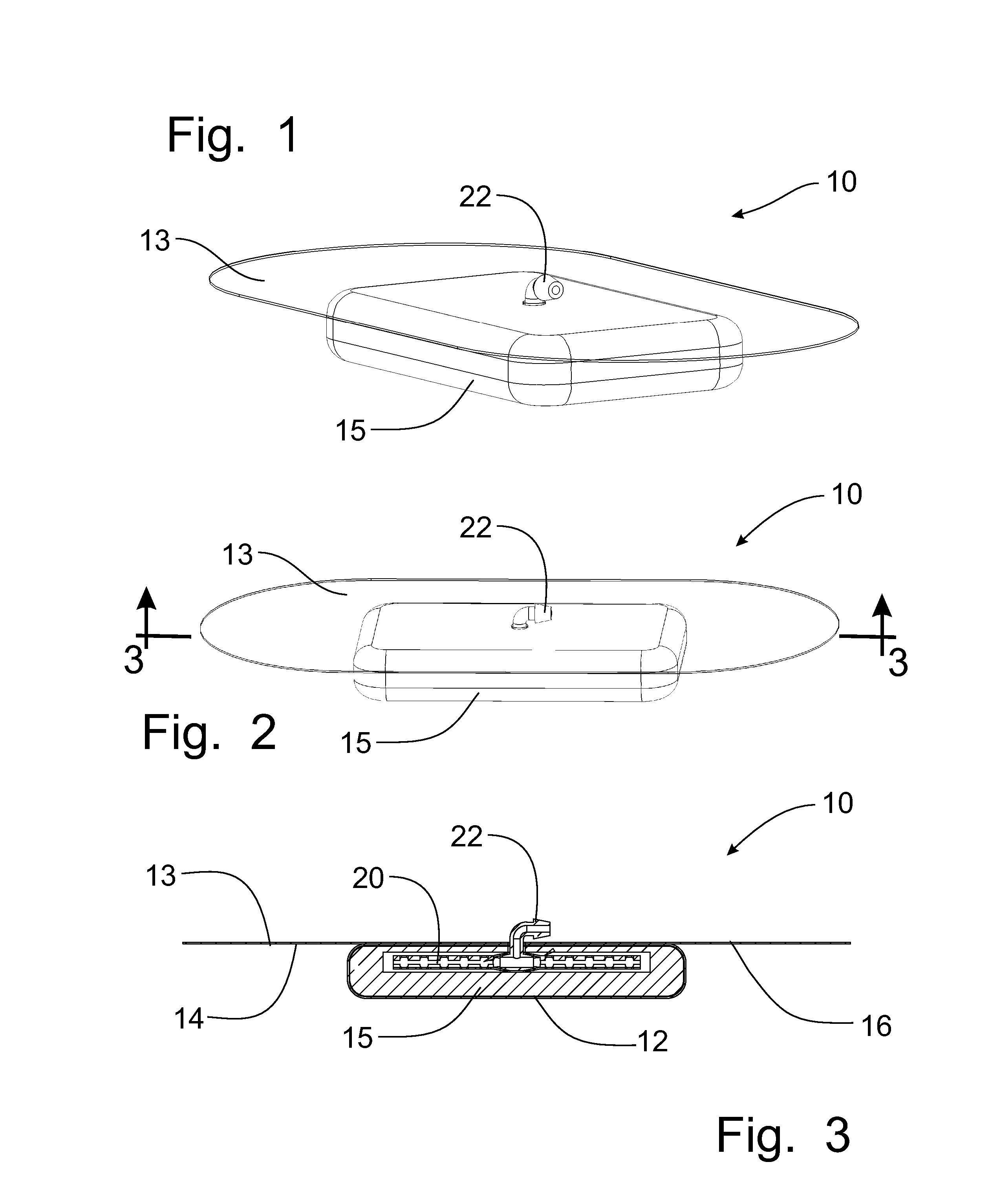
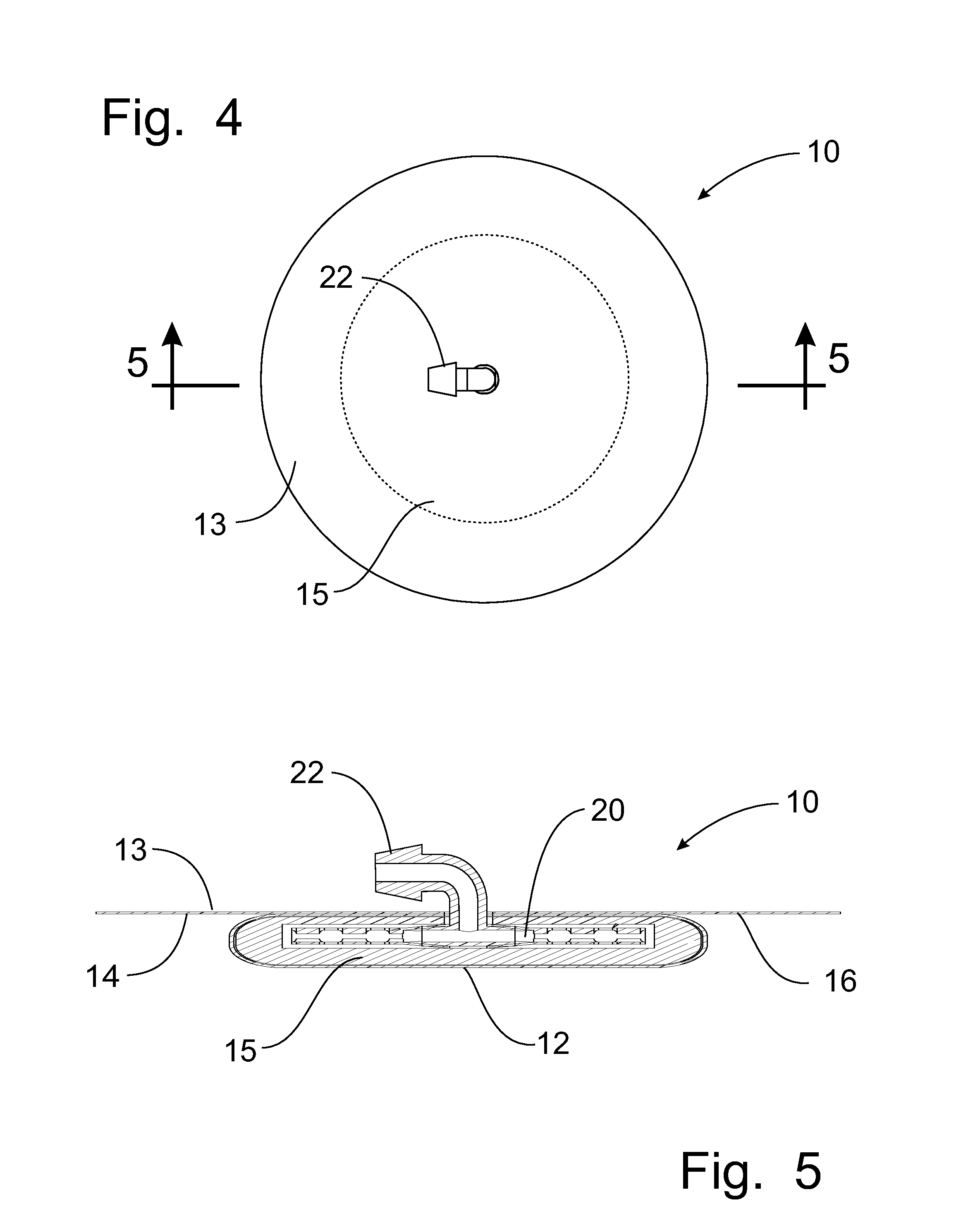
[0060]The drain tube 20 in the first embodiment depicted in FIGS. 7 and 8 is formed from a pair of opposing, relatively flat body fluid collection members 24 that are formed with slotted openings 26 in the top and bottom surfaces thereof to collect fluids and exudates from the wound through the wound contact member 15. The opposing fluid collection members 24 are connected to a central collector member 27 that forms a “T” connection with the external connector 22 so that the negative pressure applied to the connector 22 extracts the fluids and exudates from the fluid collection members 24 through the central collector member 27 and out through the connector 22 to an storage device (not shown).

second embodiment

[0061]the drain tube 20 is depicted in FIGS. 9 and 10 as a single tube configuration. The single flat body fluid collection member 24 is connected at one end thereof to the connector 22 which can pass through the seal pad 23, and also through the polyurethane film 13, for connection with the vacuum source (not shown). As depicted in the embodiment of FIGS. 7 and 8, the flat fluid collection member 24 is formed with openings 26 in the top and bottom surfaces. As depicted in FIGS. 8 and 10, the sides of the fluid collection member 24 can also be formed with openings 26 and those openings 26 can be in any shape from oval to circular, or other geometric shapes.

[0062]A first embodiment of a contoured integrated negative pressure bandage 30 is shown in FIGS. 11-13, configured for use with the patient's toes. As with the integrated bandage described above with respect to FIGS. 1-6, this contoured bandage 30 is formed with an outer polyurethane film cover 13 formed with an outer adhesive bo...


PUM


Abstract

An integrated negative pressure bandage is constructed with a non-woven polyurethane matrix pad secured on the outside surface to a sheet of polyurethane film formed with an outer adhesive boundary to establish a seal against the skin of the patient around the wound site. The inner surface of the non-woven matrix pad is covered with a silver nitrate mesh to promote healing of the wound site when the bandage is placed on top of the wound. A drain tube is contained within the non-woven matrix pad for connection with a source of negative pressure to draw the fluids and exudates from the wound for removal to a canister that is located remotely from the bandage. Contoured versions of the integrated bandage are provided for use on portions of the human body that present difficult locations for applications of negative pressure therapy, including the toes, heel, limbs, and sacral region.

Description

CROSS-REFERENCE TO RELATED APPLICATIONS[0001]This application claims domestic priority on U.S. Provisional Patent Application Ser. No. 61 / 373,233, filed on Aug. 12, 2010, the content of which is incorporated herein by reference in it entirety.FIELD OF THE INVENTION[0002]The present invention relates generally to negative pressure bandages operable to remove exudates and fluids from a wound and, more particularly, to a bandage structure that is specifically contoured to fit body parts that present difficulties in affixing and applying negative pressure bandages.BACKGROUND OF THE INVENTION[0003]Negative pressure therapy has been utilized for the treatment of a variety of wounds by medical practitioners. Conventional negative pressure bandages are generally large in size and often require the use of complicated equipment such as suction pumps, vacuum pumps and complex electronic controllers to apply a negative pressure within the bandage to draw exudates and fluids away from the wound ...

Claims


Application Information

Patent Timeline
IPC IPC(8): A61M1/00
CPCA61F13/00068A61F2013/00174A61M1/0088A61F2013/00536A61F2013/0054A61F2013/00412A61M1/915A61M1/912
Inventor BENNETT, JOHN A.BAI, JOHN-YUHANKARBOWSKI, CHRISTOPHER A.
Owner MEDU SCI
Why Eureka
Try Eureka