Hydraulic lash adjuster for internal combustion engine

a technology of internal combustion engine and lash adjuster, which is applied in the direction of functional valve types, machines/engines, transportation and packaging, etc., can solve the problems of inability to secure a sufficient amount of oil in the reservoir, and affecting the service life of the internal combustion engine. achieve the effect of enhancing resiliency

Active Publication Date: 2012-02-23
NITTAN VALVE CO LTD
View PDF1 Cites 15 Cited by
  • Summary
  • Abstract
  • Description
  • Claims
  • Application Information

AI Technical Summary

Benefits of technology

[0008]In a case where the cylindrical body 6 is not accommodated in the reservoir 28, so-called oil re-circulation phenomena (referred to leak-down phenomena) take place during operation of the engine in which the hydraulic oil is re-circulated or recycled from the high pressure chamber 29 to the reservoir 28 (communicated with the high pressure chamber 29) through a gap between the plunger 26 and the body 24 and through the small oil supply hole 27a, thereby facilitating securement of oil in the reservoir 28 when the engine is stopped. However, in the apparatus of Patent Document 1, recirculation of the leak-down oil is not performed, since the cylinder 6 is installed in the reservoir 28. Accordingly, the amount of hydraulic oil in the reservoir 28 at the time of stopping the engine will be less by the re-circulated oil.
[0040]In the device as defined in claim 5, a check valve in the form of a ball can be placed at the correct axial and circumferential position relative to the second oil supply hole, ensuring long-lasting proper opening / closing operation of the check valve for the second oil supply hole.

Problems solved by technology

A valve actuation mechanism of an internal combustion engine is in general liable to wear and / or thermal distortion that change valve gaps of the valve actuation mechanism in operation.
In actuality, however, since no hydraulic oil is supplied from the engine to the reservoir 28 while the engine is stopped, it is almost impossible then to secure a sufficient amount of oil in the reservoir 28.
As a consequence, a violent air suction phenomenon takes place when the engine is restarted.

Method used


Image

  • Hydraulic lash adjuster for internal combustion engine
  • Hydraulic lash adjuster for internal combustion engine
  • Hydraulic lash adjuster for internal combustion engine

Examples


first embodiment

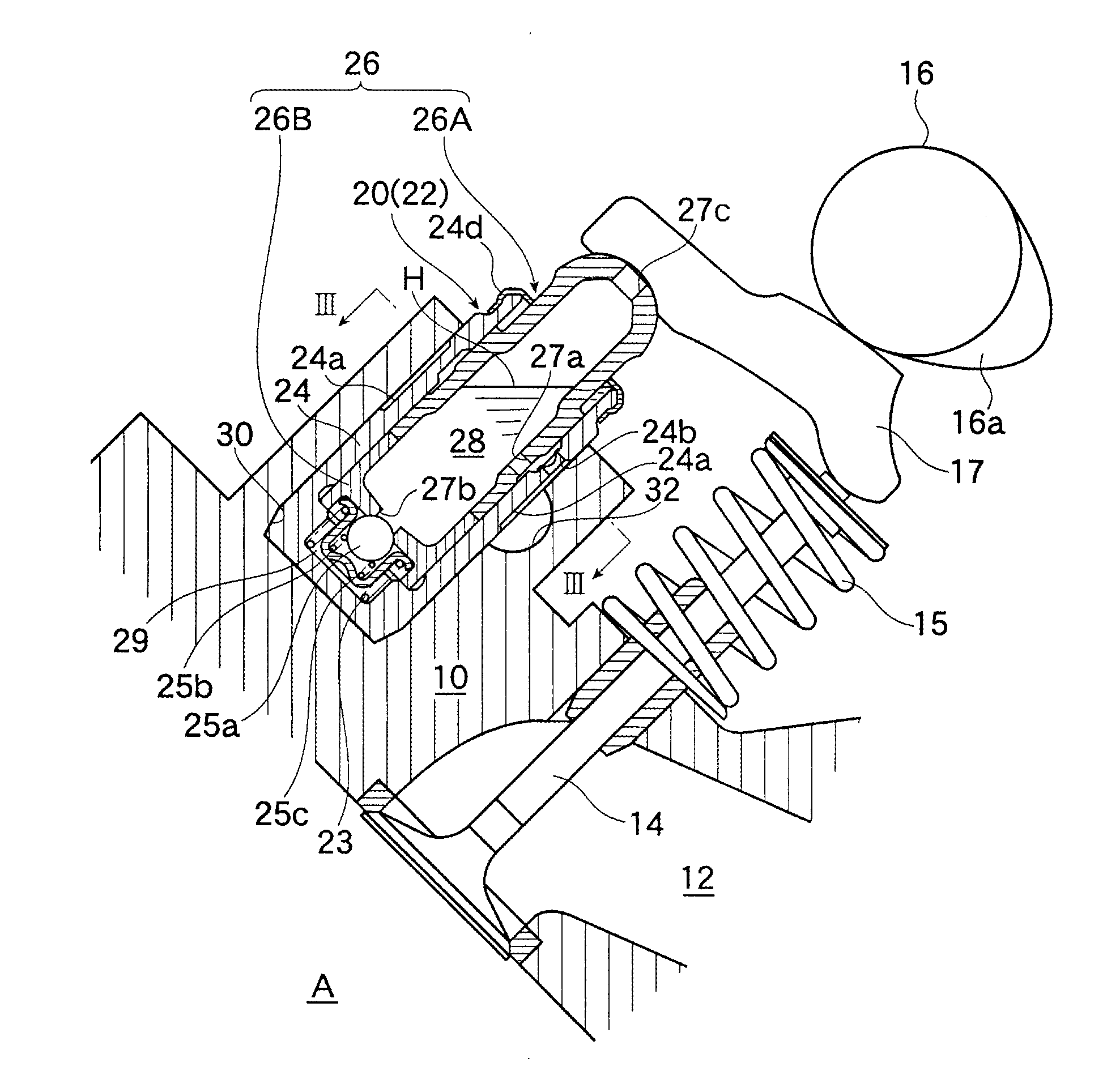
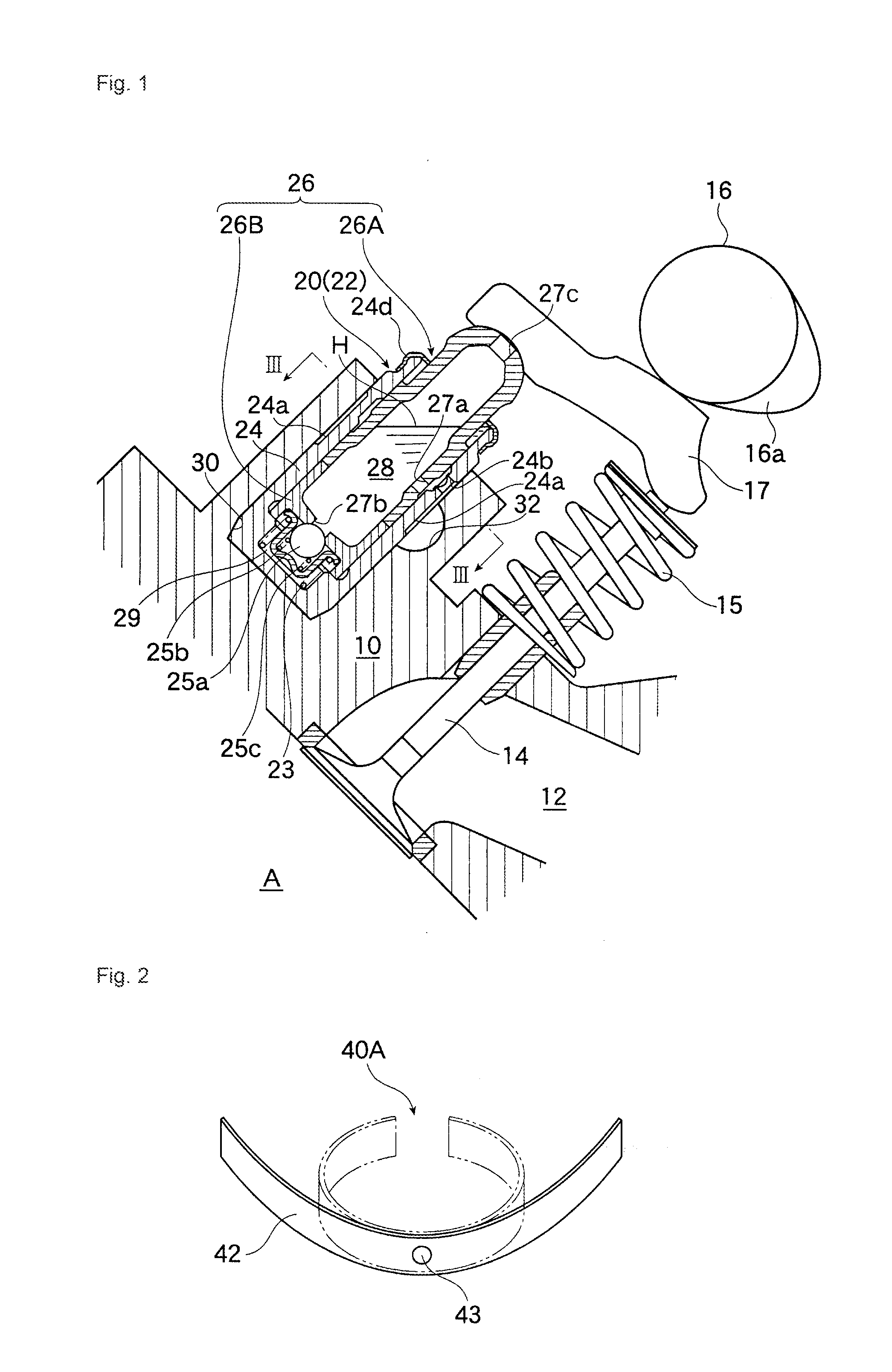
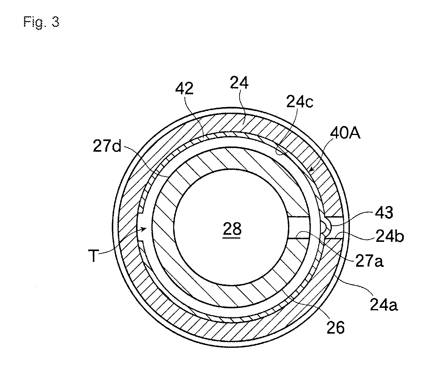
[0061]Referring to FIGS. 1 through 4, there is shown a hydraulic lash adjuster for an internal combustion engine in accordance with the invention.

[0062]In these Figures, the air supply passage 12 formed in the cylinder head 10 of the engine is connected to an opening of a combustion chamber A. The opening is closed / opened by a valve member (air intake valve) 14. The valve member 14 is urged by a spring 15 to close the opening of the air supply passage 12. The top end of the valve member 14 abuts against a rocker arm 17 rocked by the rotation of the cam 16. The cam 16 has a cam nose 16a.

[0063]Provided adjacent the valve member 14 is a hydraulic lash adjuster 20, which comprises a lash adjuster body 22 inserted in an adjuster mounting bore 30 formed in the cylinder head 10. The adjuster mounting bore 30 has an upper open end and a closed lower end (bottom). The lash adjuster body 22 primarily consists of a cylindrical body 24 having an upper open end and a lower bottom end, and a plu...

second embodiment

[0080]Referring to FIG. 5 through 7, there is shown a hydraulic lash adjuster in accordance with the invention.

[0081]In the second embodiment, the body 24 is provided with two second oil supply holes 24b spaced apart at equal angular intervals along an inner circumference of the sidewall of the body 24, while a leaf spring 42 constituting a check valve 40B is provided at two longitudinal positions thereof with two engagement protrusions 43 such that they can fit in the respective second oil supply holes 24b when the leaf spring is fit in the circumferential groove formed in the sidewall of the body 24.

[0082]During operation of the engine, the hydraulic oil stored in the oil gallery 32 is led to the pair of the oil supply holes 24b via the circumferential groove 24a formed in the outer circumferential sidewall of the body 24. The pressurized oil exerts an radially inward pressure on the surrounding regions of the paired engagement protrusions 43 of the check valve 40B in engagement w...

third embodiment

[0085]Referring to FIGS. 8 and 9, there is shown a hydraulic lash adjuster for an internal combustion engine in accordance with the invention.

[0086]In the third embodiment, a leaf spring 42 constituting a check valve 40C is provided with elongate slits 42a in the regions other than the opposite ends thereof and the surrounding regions of the engagement protrusions 43. The check valve 40C is designed to allow quick flow of pressurized hydraulic oil through the second oil supply holes 24b and the annular communication passage T when the check valve 40C is opened.

[0087]When the engine is in operation, the surrounding regions of the engagement protrusions 43 of the leaf spring 42 is displaced away from the respective peripheries of the second oil supply holes 24b by the pressurized oil led to the second oil supply holes 24b (in a manner as shown in FIG. 4(b)), so that the pressurized oil flowing into the circumferential groove 24c enters the annular communication passage T not only thro...


PUM


Abstract

OBJECTTo provide a hydraulic lash adjuster capable of retaining a large amount of hydraulic oil, in a reservoir communicated with a high-pressure chamber when the engine is stopped.MEANS FOR SOLVING THE PROBLEMA hydraulic lash adjuster including: a cylindrical body (24) having an upper open end, a closed bottom, and a second oil supply hole (27a) formed in the sidewall of the cylindrical body; and a plunger having a top end serving as a plunging end, a sidewall, a bottom end, a high pressure chamber (29) at the lower bottom, and a first oil supply hole (24b) formed in the sidewall, the plunger being slidable on the inner wall of the body. The plunger has a reservoir (28) that communicates with an external oil supply line (32) via the first oil supply hole (24b) and the second oil supply hole (27a). The lash adjuster is provided with a check valve (40a) for opening the oil supply hole (24b) by the oil pressure led from an external oil passage (32) to the oil supply hole (24b). The check valve (40a) is arranged in an annular communication passage (T) formed between the sidewalls of the plunger (26) and the body (24) for communicating the oil supply hole (27a) with the oil supply hole (24b). Leak-down oil is recycled while the engine is in operation. When the engine is stopped, the check valve (40A) closes the oil supply hole (24b). Accordingly, a large amount of hydraulic oil is stored in the reservoir (28) communicated with the high pressure chamber (29), with the oil level H in the reservoir (28) never being lower than the open end of the body (24).

Description

FIELD OF THE INVENTION[0001]This invention relates to a hydraulic lash adjuster for automatically compensating for the valve gap of a valve actuation mechanism of an internal combustion engine, and more particularly, the invention relates to a hydraulic lash adjuster capable of retaining a large amount of hydraulic oil in a reservoir in communication with a high pressure chamber provided in the hydraulic lash adjuster when the engine is stopped.BACKGROUND ART[0002]A valve actuation mechanism of an internal combustion engine is in general liable to wear and / or thermal distortion that change valve gaps of the valve actuation mechanism in operation. To properly compensate for such change in valve gap, a hydraulic lash adjuster may be used.[0003]FIG. 19 shows a conventional hydraulic lash adjuster, which has a body 2 (hereinafter referred to as adjuster body 2) mounted in a mounting bore 30 formed in a cylinder head 10 of the engine. The adjuster body 2 comprises a body 24 fitted in the...

Claims


Application Information

Patent Timeline
Patent Type & Authority Applications(United States)
IPC IPC(8): F01L1/245
CPCF01L1/185F01L1/2405Y10T74/2107F16K15/142F16K15/04F01L1/24F01L1/245
Inventor KUBOTA, YUKIOTANAKA, AKIFUMI
Owner NITTAN VALVE CO LTD
Why Eureka
Try Eureka