Dry vacuum cleaning appliance

Inactive Publication Date: 2012-02-23
SKAGIT NORTHWEST HLDG INC
View PDF5 Cites 11 Cited by
  • Summary
  • Abstract
  • Description
  • Claims
  • Application Information

AI Technical Summary

Benefits of technology

[0019]The present invention overcomes limitations of the prior art by providing a novel in-line bagless dry vacuum cleaning appliance for operation with the fluid cleaning head of a fluid cleaning appliance for initial dry vacuum cleaning of carpet and other flooring surfaces, wall surfaces and upholstery. Accordingly, the novel in-line bagless dry vacuum cleaning appliance of the invention eliminates the need for either a completely independent dry vacuum cleaner appliance (not shown) for re

Problems solved by technology

Unfortunately, because the blowers generating the vacuum in professional fluid cleaning appliances operate at such high pressures and close mechanical tolerances, any loose dry dust and debris can easily clog them, and if clogged, the blower can quickly burn-out and be destroyed, rendering the cleaning system inoperative.
Therefore, the vacuum function of professional fluid cleaning appliances is not operated dry for fear of clogging and burning-out the very sensitive high pressure blower.
Again, the fluid cleaning vacuum source is not utilized for dry vacuum cleaning because of the danger to the high pressure blowers if they become clogged by dust and dirt carried in the intake airstream.
Neither of these conventional dry vacuum cleaning options is satisfactory since each requires the operator to at least bring in a separate vacuum source, if not a complete dry vacuum system independently of the fluid cleaning appliance.
However, this is

Method used


Image

  • Dry vacuum cleaning appliance
  • Dry vacuum cleaning appliance
  • Dry vacuum cleaning appliance

Examples


Example

[0038]For the purposes of promoting an understanding of the principles of the invention, reference will now be made to the exemplary embodiments illustrated in the drawings, and specific language will be used to describe the same. It will nevertheless be understood that no limitation of the scope of the invention is thereby intended. Any alterations and further modifications of the inventive features illustrated herein, and any additional applications of the principles of the invention as illustrated herein, which would occur to one skilled in the relevant art and having possession of this disclosure, are to be considered within the scope of the invention.

[0039]In the Figures, like numerals indicate like elements.

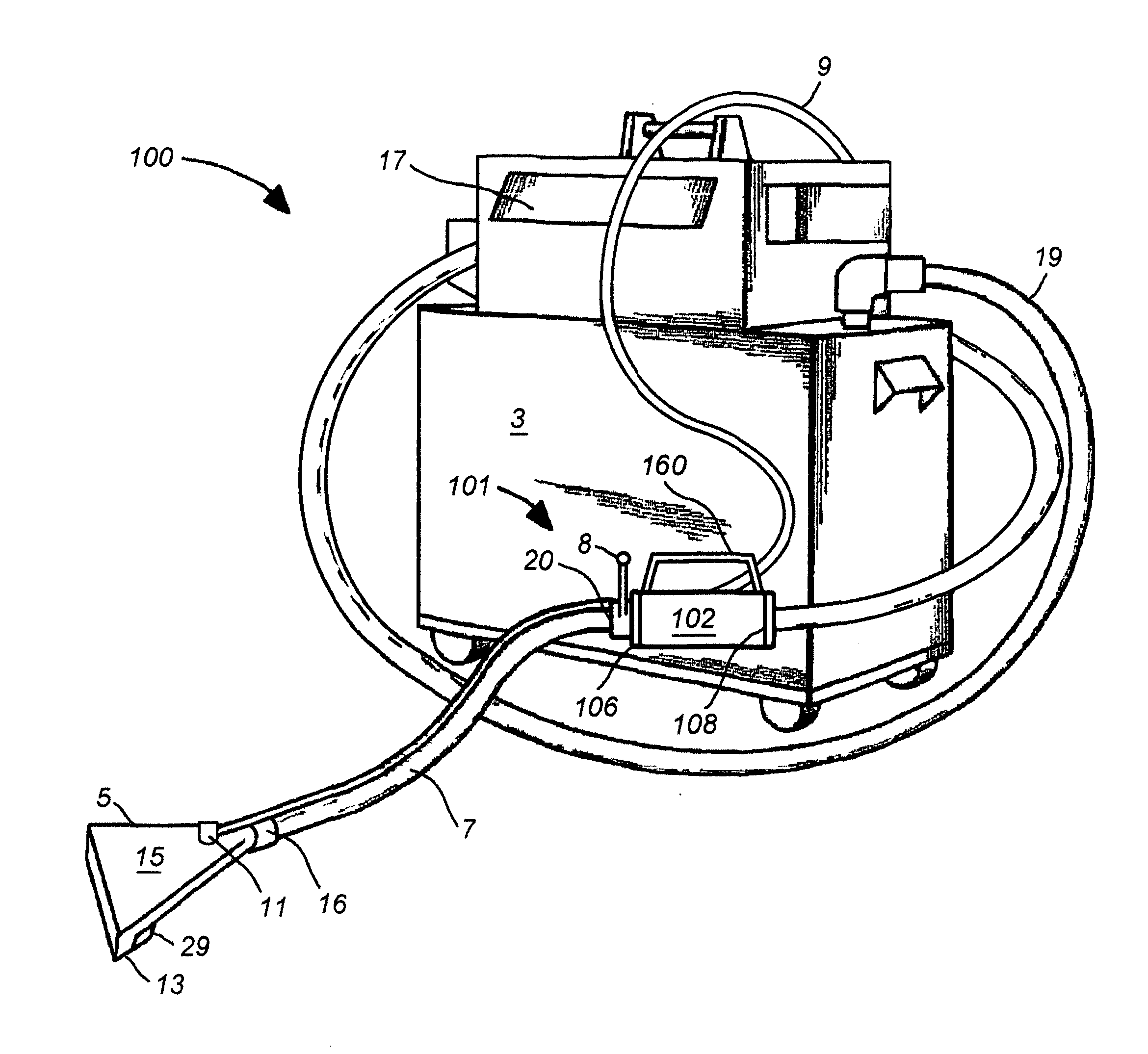
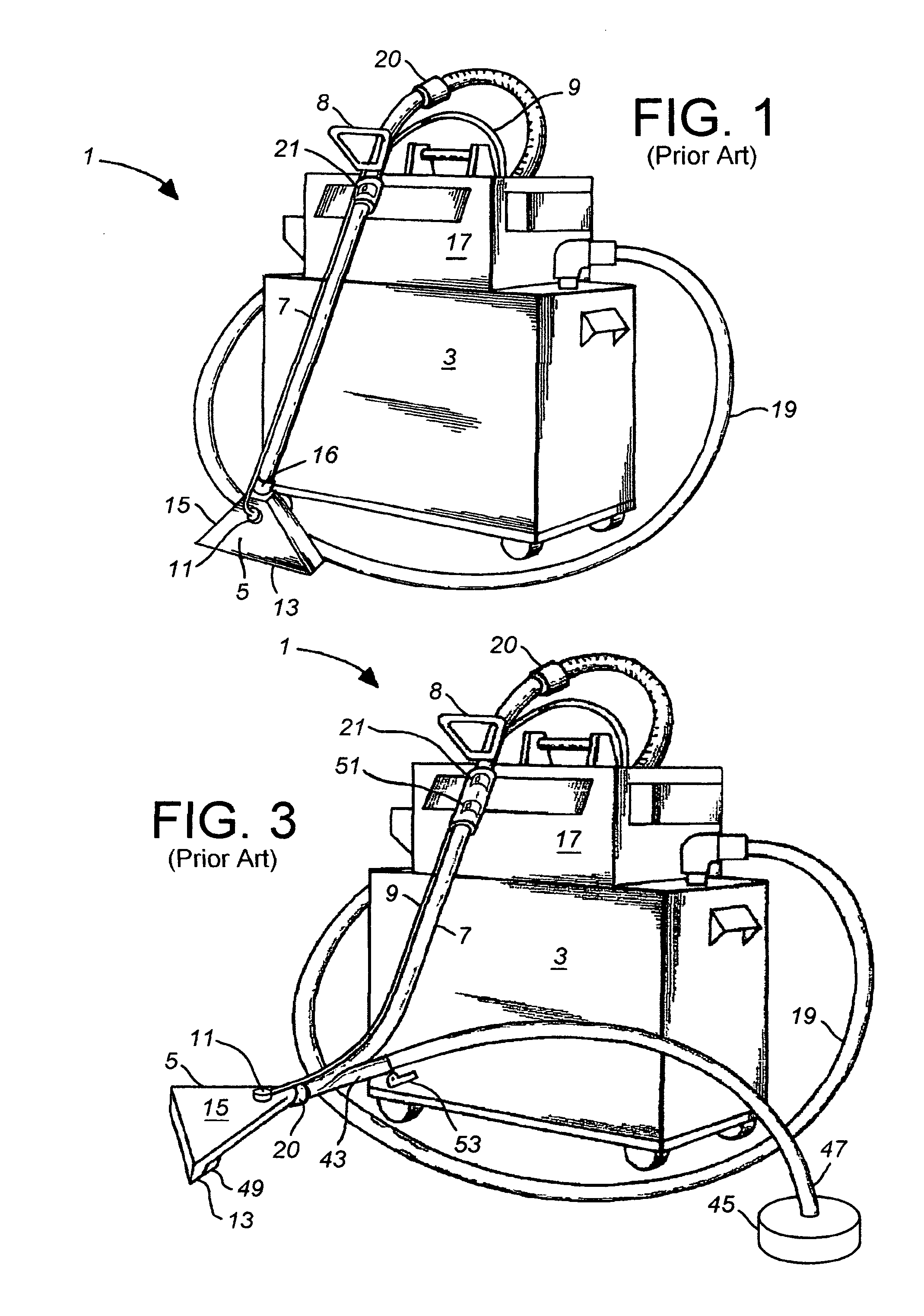
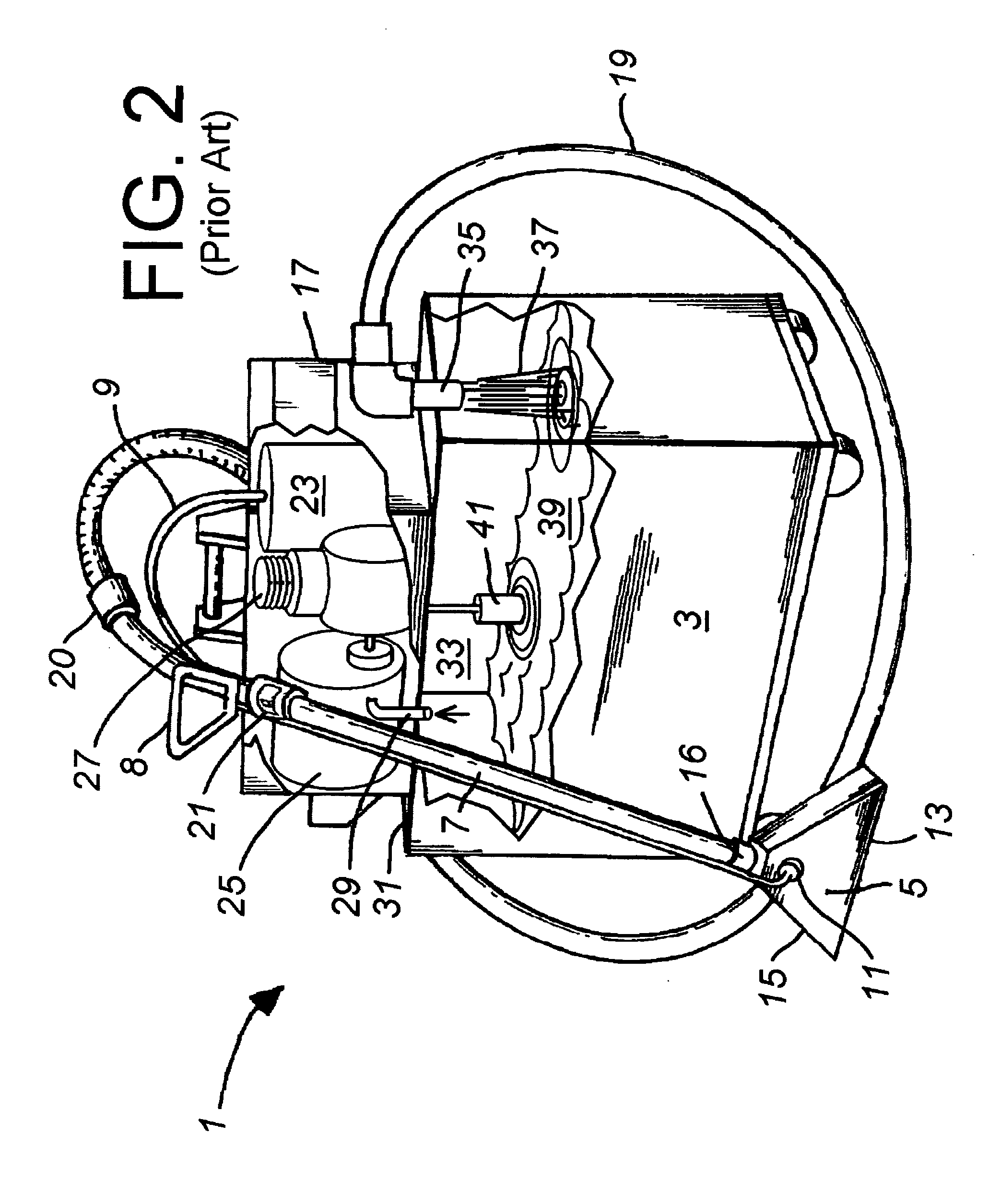
[0040]FIG. 4 is an exemplary illustration of a combination dry / fluid cleaning appliance 100 having a novel in-line bagless dry vacuum cleaning appliance 101 in combination with fluid cleaning system 1 of the types illustrated in FIGS. 1 and 2, whereby it is unnecessary to p...


PUM


Abstract

An in-line bagless dry vacuum cleaning appliance having a vacuum conduit within a separator tube, the vacuum conduit having spaced apart first and second vacuum suction apertures communicating with an exhaust connector; a cyclone chamber communicating with an intake connector and encompassing the first vacuum suction apertures for forming a cyclonic flow region between the central vacuum conduit and an interior wall of the separator tube; a particle receiving chamber communicating with the cyclone chamber; an axial cyclone inlet communicating between the cyclone chamber and the intake connector of the separator tube; a particle separator dividing the particle receiving chamber from the cyclone chamber and forming a first transfer gap therebetween adjacent to the interior wall of the separator tube for receiving disentrained particles into the particle receiving chamber from the cyclone chamber; and a filter between the particle receiving chamber and the second vacuum suction aperture.

Description

FIELD OF THE INVENTION[0001]The present invention to bagless dry vacuum cleaning appliances for cleaning surfaces, and in particular to a bagless dry vacuum cleaning appliance and method for operation in combination with a fluid cleaning appliance for dry vacuum cleaning carpet and other flooring surfaces of dust and debris.BACKGROUND OF THE INVENTION[0002]Many fluid cleaning appliances, such as the system illustrated herein, are known for cleaning carpeting and other flooring, wall and upholstery surfaces. The cleaning apparatuses and methods most commonly used today apply cleaning fluid as a spray under pressure to the surface whereupon the cleaning fluid dissolves the dirt and stains and the apparatus scrubs the fibers while simultaneously applying a vacuum or negative pressure to extract the cleaning fluid and the dissolved soil. A high pressure blower is used to generate the strong vacuum necessary for extracting the soiled cleaning fluid and rout it to the cleaning unit's wast...

Claims


Application Information

Patent Timeline
IPC IPC(8): A47L9/10B08B5/04
CPCA47L5/225A47L5/36A47L9/1608A47L9/1683A47L9/248B04C2009/004A47L11/4022A47L11/4044B04C3/06B04C2003/006A47L11/34
Inventor STUDEBAKER, ROY
Owner SKAGIT NORTHWEST HLDG INC
Why Eureka
Try Eureka