Capacitive sensors for monitoring loads

a technology of capacitor plates and load monitoring, which is applied in the direction of instruments, force/torque/work measurement apparatus, instruments, etc., can solve the problems of relative displacement of inner and outer capacitor plates, and achieve the effects of increasing signal strength, increasing reliability and accuracy, and increasing sensitivity and accuracy

Active Publication Date: 2012-02-23
THE BF GOODRICH CO
View PDF9 Cites 14 Cited by
  • Summary
  • Abstract
  • Description
  • Claims
  • Application Information

AI Technical Summary

Benefits of technology

[0010]The interior bore can extend along about half of the length of the main pin, or any other suitable portion of the length. The core pin can therefore be cantilevered to the interior bore proximate a middle portion of the main pin. The capacitor can be located proximate the second, or free end of the main pin. It is also contemplated that the interior bore can extend through the entire length of the main pin, wherein the core pin is mounted to the interior bore proximate the first end of the main pin, and wherein the capacitor is located proximate the second end of the main pin. An electronics housing can be included on an end of the main pin proximate the capacitor for holding electronic components in electrical communication with the capacitor, for example if the added volume is needed. The electronics housing can be axially eccentric or concentric with respect to the axial interior bore of the main pin. It is also contemplated that the main pin can include an angle sensor for monitoring change in the relative angle between the strut lug and the torque link. The angle sensor can be mounted in an end of the main pin opposite the end with the capacitor or can be included in the load sensing end, for example if the electronics are recessed enough into the main pin to provide adequate volume for the angle sensor as well. An angle sensor can be mounted, for example, in the axial interior bore of the main pin between the capacitor and the first end of the main pin. The core pin, capacitor, and angle sensor can be mounted proximate the first end of the main pin. A second such core pin, capacitor, and angle sensor can be mounted proximate the second end of the main pin for increased reliability and accuracy.
[0011]In certain embodiments, one or more additional outer capacitor plates can be included, each being mounted to the main pin. The outer capacitor plates can each be substantially aligned circumferentially and axially with the inner capacitor plate. Each of the outer capacitor plates can be configured and adapted to be connected to an electrical circuit to produce signals indicative of external loading on the main pin as described above. The outer capacitor plates can be spaced apart substantially evenly circumferentially. With three or more outer capacitor plates, signals indicative of load magnitude and applied angle can be produced. Signals from opposed outer capacitor plates can be constructively combined, wherein the signals are read differentially to increase signal strength for added sensitivity and accuracy.

Problems solved by technology

Relative displacement of the core pin and the main pin due to external loading on the main pin, e.g., from the torque link and strut lug, results in relative displacement of the inner and outer capacitor plates.

Method used


Image

  • Capacitive sensors for monitoring loads
  • Capacitive sensors for monitoring loads
  • Capacitive sensors for monitoring loads

Examples


Embodiment Construction

[0028]Reference will now be made to the drawings wherein like reference numerals identify similar structural features or aspects of the subject invention. For purposes of explanation and illustration, and not limitation, a partial view of an exemplary embodiment of a sensor which has been constructed in accordance with the invention is shown in FIG. 4 and is designated generally by reference character 100. Other embodiments of sensors in accordance with the invention, or aspects thereof, are provided in FIGS. 5-9, as will be described. The systems and methods of the invention can be used, for example, to monitor loads acting on landing gear structures, such as struts.

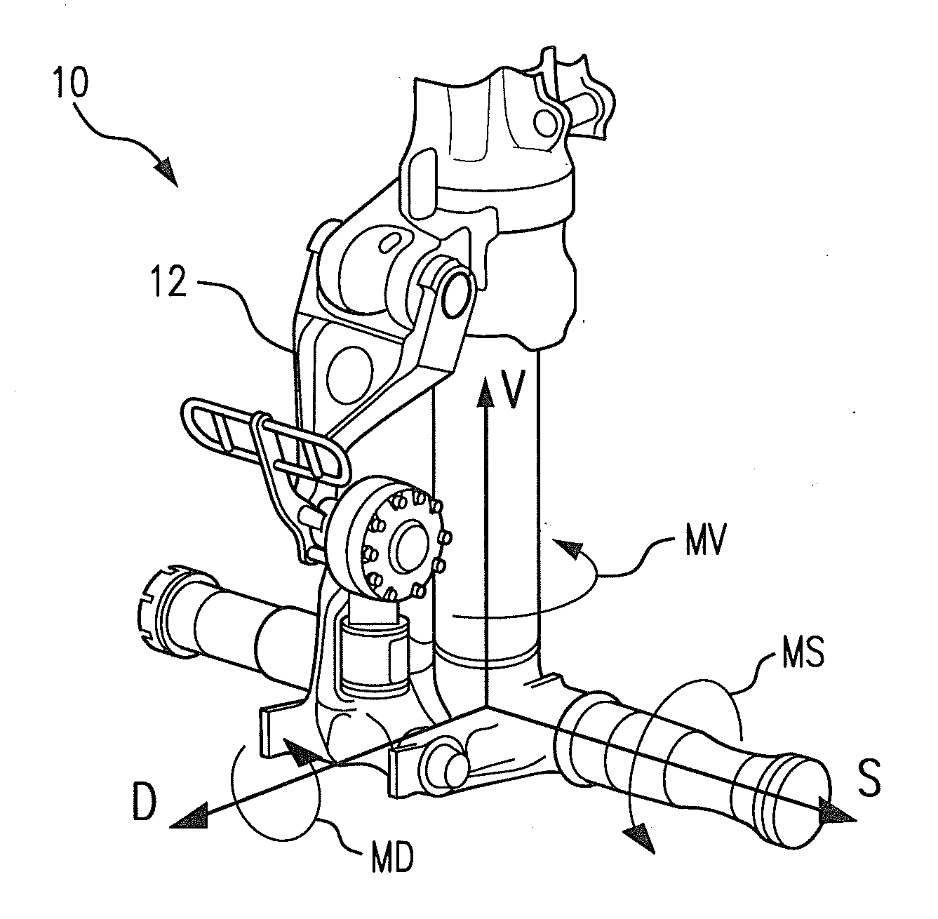
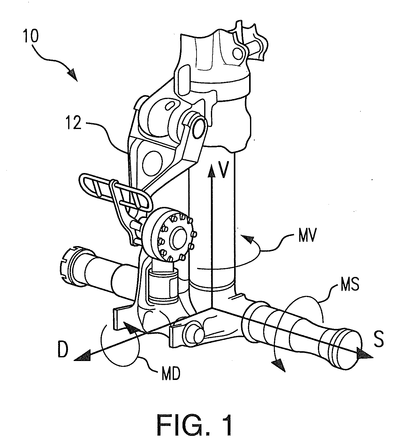
[0029]With reference now to FIG. 1, there is a need to monitor linear loads and rotational moments in aircraft landing gear structures. The complete application of an overload detection system to a landing gear structure requires measurement of loading in six dimensions, or degrees of freedom. An exemplary landing gear ...


PUM


Abstract

A sensor for monitoring loads in a landing gear torque linkage includes a main pin having an axial interior bore defined therein. The main pin is configured and adapted to engage a torque link to a strut lug of a landing gear strut. A core pin is mounted axially within an interior bore of the main pin and is spaced radially inwardly from the interior bore for relative displacement with respect to the main pin. A capacitor is included having an inner capacitor plate mounted to the core pin. An outer capacitor plate is mounted to the main pin. Relative displacement of the core pin and the main pin due to loads acting on the torque link and strut lug results in relative displacement of the inner and outer capacitor plates. Signals can thereby be produced indicative of the loads acting on the torque link.

Description

CROSS-REFERENCE TO RELATED APPLICATIONS[0001]This application is a continuation-in-part of U.S. patent application Ser. No. 12 / 857,793 filed Aug. 17, 2010. This application claims benefit of priority to U.S. Provisional Patent Application No. 61 / 393,456 filed Oct. 15, 2010. Reference is also made herein to U.S. patent application Ser. No. 12 / 839,401 filed Jul. 19, 2010, to U.S. patent application Ser. No. 12 / 839,216 filed Jul. 19, 2010, and to U.S. patent application Ser. No. 12 / 839,170 filed Jul. 19, 2010. Each of the applications above is incorporated by reference herein in its entirety.BACKGROUND OF THE INVENTION[0002]1. Field of the Invention[0003]The present invention relates to monitoring loads in load bearing members, and more particularly to sensors for monitoring loads in landing gear torque links.[0004]2. Description of Related Art[0005]There is a need to monitor loading in landing gear structures of aircraft to determine if the load bearing members are ever overloaded. Th...

Claims


Application Information

Patent Timeline
Patent Type & Authority Applications(United States)
IPC IPC(8): B64C25/02G01B7/16
CPCB64C25/001B64C2025/006G01L5/0014G01L1/142B64D2045/008
Inventor ERIKSEN, ODD HARALD STEENSANDEN, CHRISTOPHER
Owner THE BF GOODRICH CO
Why Eureka
Try Eureka