
Single plane compton camera

a single plane, compton camera technology, applied in the field of apparatus and methods for radiation measurement, can solve the problems of large size of conventional compton camera, cumbersome field use, and expense of detection efficiency, and achieve the effects of simple computational methods, improved detection efficiency, and compact layou

Inactive Publication Date: 2012-02-23
GUEORGUIEV ANDREY +4
View PDF1 Cites 20 Cited by
  • Summary
  • Abstract
  • Description
  • Claims
  • Application Information

AI Technical Summary

Benefits of technology

[0012]Objects of the present invention include the following: providing a Compton camera having improved detection efficiency; providing a Compton camera having the ability to locate the position of a radiation source using relatively simple computational methods; providing a Compton camera having a relatively compact layout; providing a Compton camera having relatively few detection elements; providing a Compton camera that is easily scalable to create the most compact device for a given absolute efficiency; providing a method for locating a radiation source using a Compton camera having a relatively compact overall size and using relatively simple computational methods; and, providing a method for locating a radiation source using a Compton camera having a single detection plane. These and other objects and advantages of the invention will become apparent from consideration of the following specification, read in conjunction with the drawings.
[0013]Accord

Problems solved by technology

The two planes are typically separated by a distance that ranges from 30 cm to perhaps 1 m; as a consequence, many conventional Compton cameras are very large devices and are cumbersome to use in the field.
The coded aperture design geometrically reduces the uncertainty of the Compton angle, but at the expense of detection efficiency.

Method used


Image

  • Single plane compton camera
  • Single plane compton camera
  • Single plane compton camera

Examples


example

[0067]It will be appreciated that medical imaging using PET, CT, or other methods may benefit from utilizing this invention. Current methods using gross counters may neglect absorption events that deposit energies less than some threshold. Using the creation of sum spectra through coincident events occurring in adjacent detectors may reduce the total number of photons necessary for imaging, which will reduce the radiation dose applied to the patient during the imaging procedure.

[0068]Those skilled in the art will appreciate that the invention provides numerous advantages over conventional methods. Some of the advantages include:[0069]1. High intrinsic efficiency for Compton scattering[0070]2. The probability for coupled Compton scattering and photoelectric absorption events between detectors is higher than for separate planes over the entire energy range[0071]3. Field of view is nearly 180° in the X- and Y-directions[0072]4. Low number of counts required to determine the source dire...


PUM


Abstract

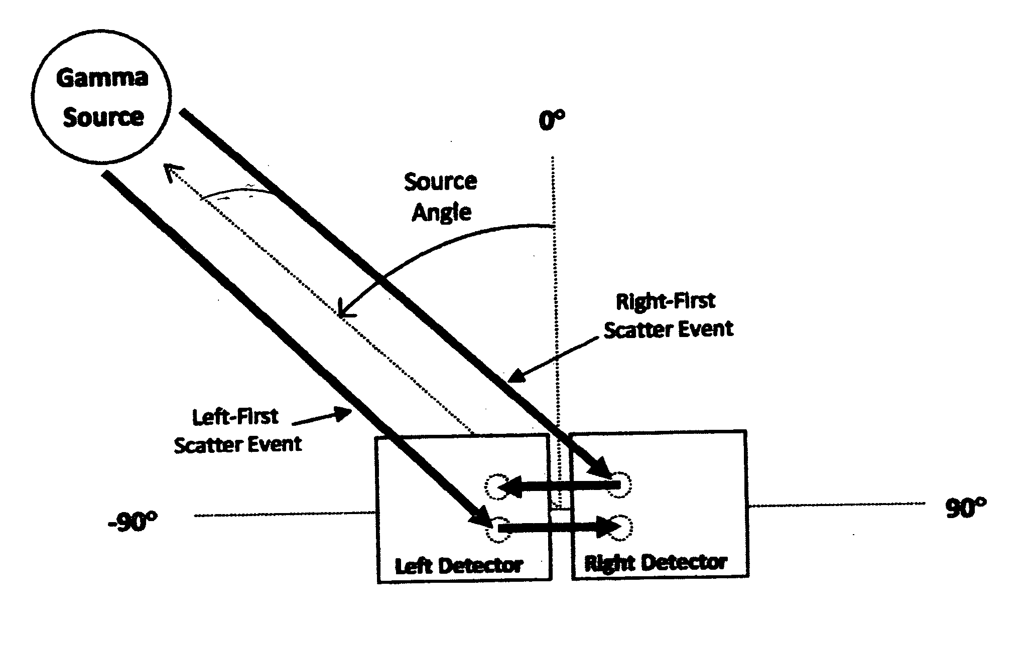
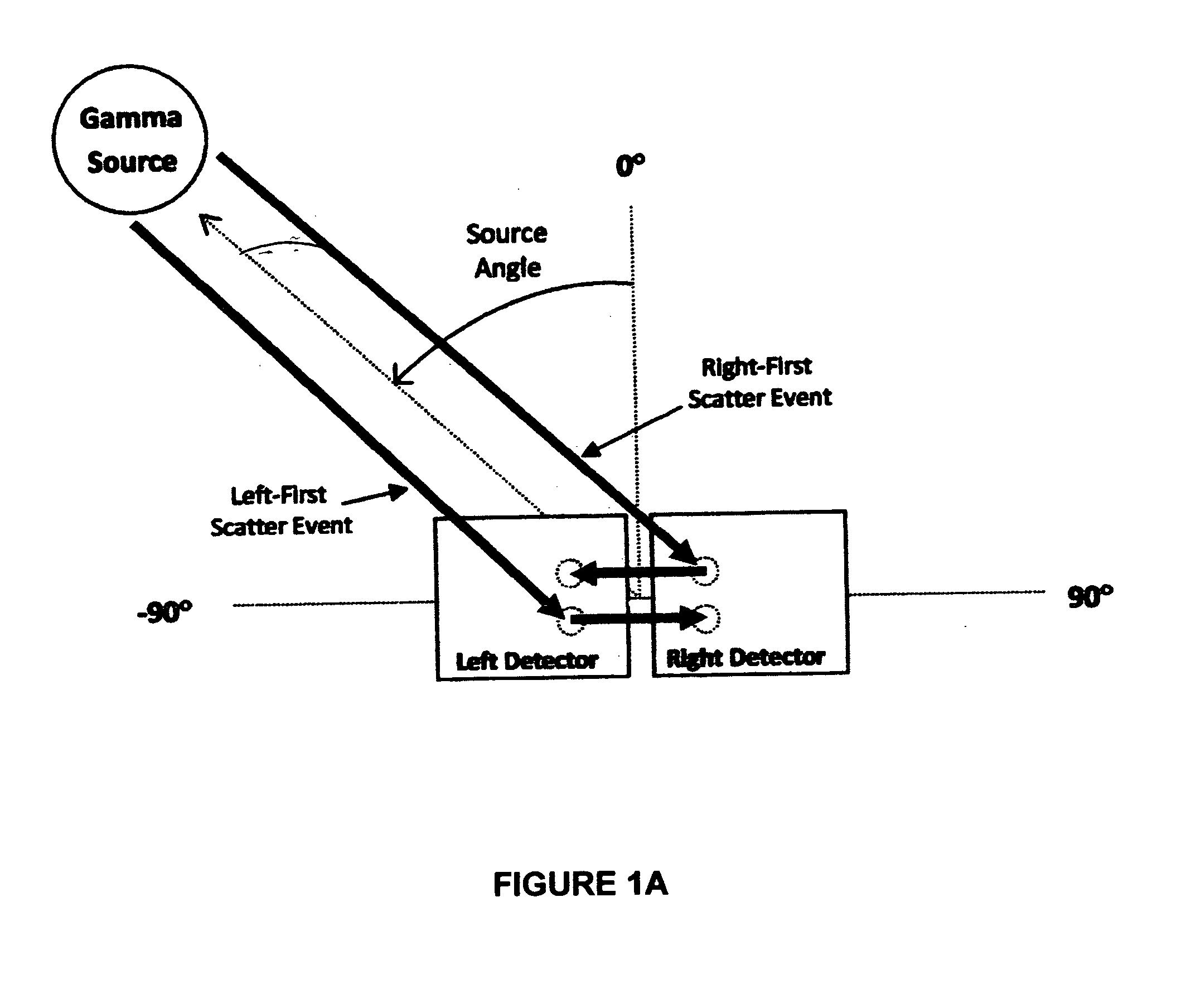
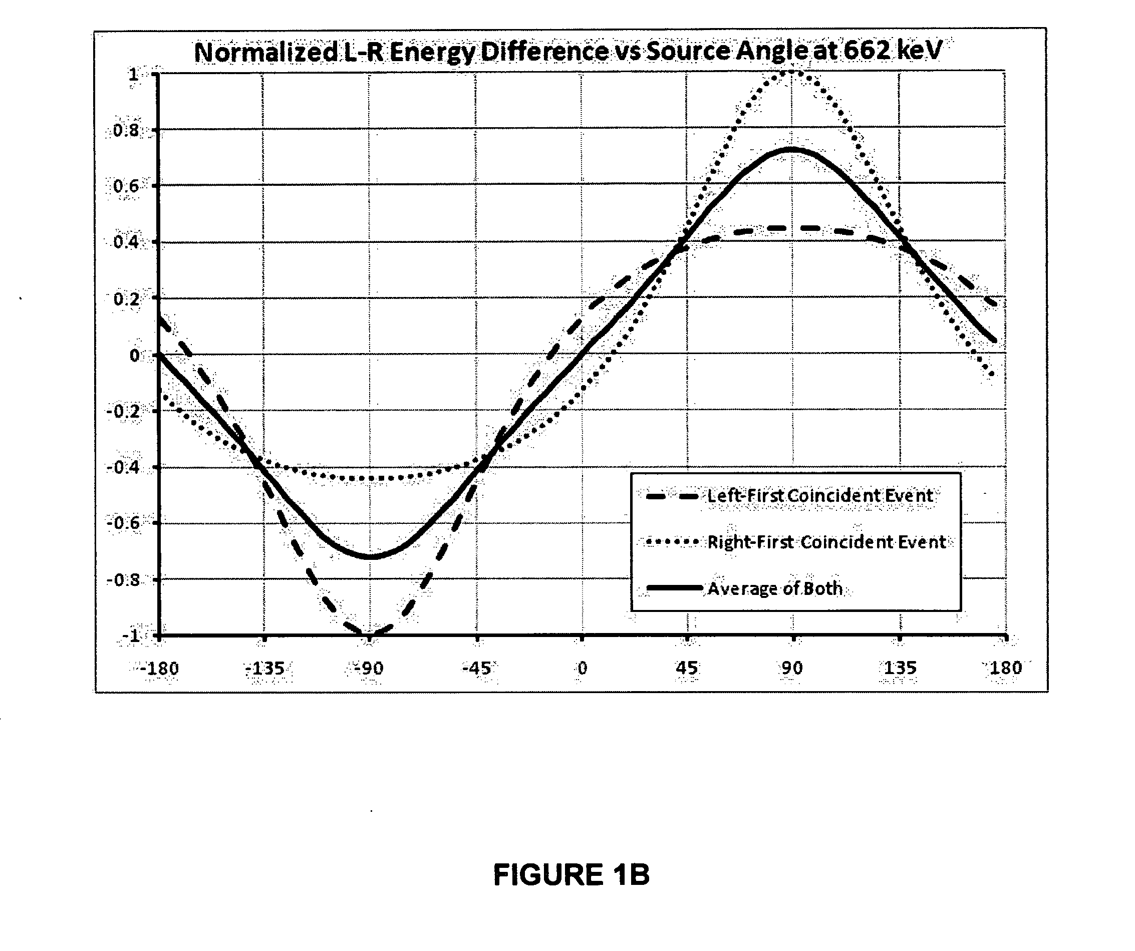
A single plane Compton telescope uses a coplanar array of detectors to determine the direction of a radiation source. Detector materials and dimensions may have comparable Compton scattering and photoelectric absorption probabilities, so scattered photons have a high probability of escape from the detector in which the initial interaction occurs, while being absorbed in adjacent detectors. Energy information from coincident interactions between two detectors defines a bearing plane that contains the radiation source; by comparing these interactions in two non-parallel directions, the source is localized to a line representing the intersection of two bearing planes. Energies may be summed to determine the initial photon energy. The array may be of a single detector type or an arrangement of different detector types. The array may be a stationary, planar configuration of at least three detectors, or a linear array of at least two detectors that is rotatable within a selected plane.

Description

BACKGROUND OF THE INVENTION[0001]1. Field of the Invention[0002]The invention pertains to apparatus and methods for radiation measurement, and more particularly to apparatus and methods to resolve the position and direction of a distant radiation source.[0003]2. Description of Related Art[0004]In the field of radiation measurement, it is often desirable to determine the location of a radiation source; this is particularly true in applications involving safety or security, in which there is a need to quickly locate a radioisotope that is concealed, for example, in a vehicle passing near a screening point. Because many isotopes of interest emit gamma radiation, conventional detectors frequently make use of the phenomenon of Compton scattering and are referred to as Compton cameras or Compton telescopes.[0005]The Compton telescope design originates with the discovery of Compton scattering. Incident radiation is scattered upon interaction with a detector that records the energy of the C...

Claims


Application Information

Patent Timeline
IPC IPC(8): G01T1/20G01T1/26
CPCG01T1/2907
Inventor GUEORGUIEV, ANDREYSTEIN, JUERGENPRESTON, JEFFREY R.HOY, LESLIE D.HERBACH, CLAUS-MICHAEL
Owner GUEORGUIEV ANDREY
Learn More