Stereoscopic video display apparatus and stereoscopic video display method

a technology of stereoscopic video and display method, which is applied in the field of stereoscopic video display apparatus, can solve the problems of high probability that one or some viewers suffer(s) from pseudo stereoscopy, and achieve the effects of suppressing the occurrence of pseudo stereoscopy, reducing the area size of crosstalk, and simple structur

Active Publication Date: 2012-02-23
PANASONIC INTELLECTUAL PROPERTY CORP OF AMERICA
View PDF7 Cites 92 Cited by
  • Summary
  • Abstract
  • Description
  • Claims
  • Application Information

AI Technical Summary

Benefits of technology

[0051]The stereoscopic video display apparatus may be a stereoscopic video display apparatus which enables n number of viewers (even in the case of three or more viewers) to watch a stereoscopic video without causing pseudo stereoscopy, by controlling the display positions of n+1 number of parallax images on a display panel depending on the detected positions of the heads of the viewers.
[0052]The stereoscopic video display apparatus may divide the position intervals between the predetermined display positions of the parallax images in the sets such that the position intervals are smaller than the inter-eye distances of the respective viewers. The stereoscopic video display apparatus may control the display positions of a number (obtained according to n×m+1) of parallax images according to the number of position interval segments m on the display panel depending on the detected head positions. This enables three or more viewers to watch a stereoscopic video without causing pseudo stereoscopy, and enables reduction in the area size of crosstalk which is produced between the predetermined positions.
[0053]Furthermore, the stereoscopic video display apparatus may prepare only a set of a left-eye image L and a right-eye image R, and depending on the number of viewers (for example, three or more viewers), perform interpolation using the L and R parallax image set to generate and use interpolated parallax images without preparing other parallax images required depending on the number of viewers. This enables t

Problems solved by technology

However, in the case of three or more viewers, it is highly likely

Method used


Image

  • Stereoscopic video display apparatus and stereoscopic video display method
  • Stereoscopic video display apparatus and stereoscopic video display method
  • Stereoscopic video display apparatus and stereoscopic video display method

Examples


embodiment 1

[0090]With reference to FIG. 1 to FIG. 8, Embodiment 1 describes an apparatus which displays a stereoscopic video by controlling, using plural parallax images whose number is obtained according to the number of viewers+1, the display positions of parallax images on a display panel based on the detected head positions of the viewers of the parallax images.

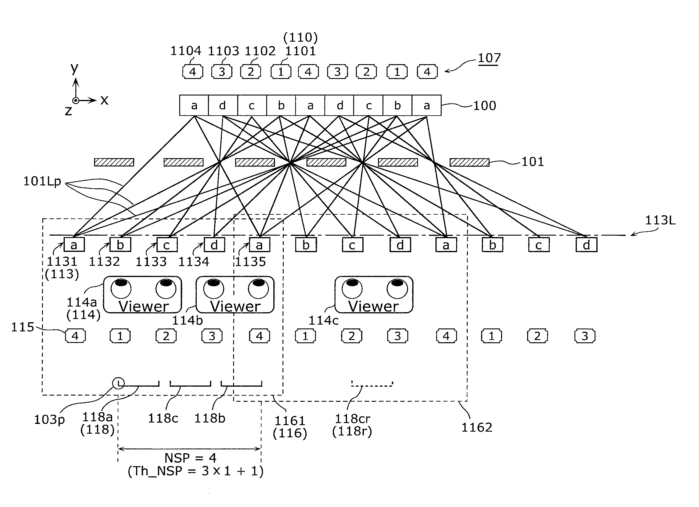
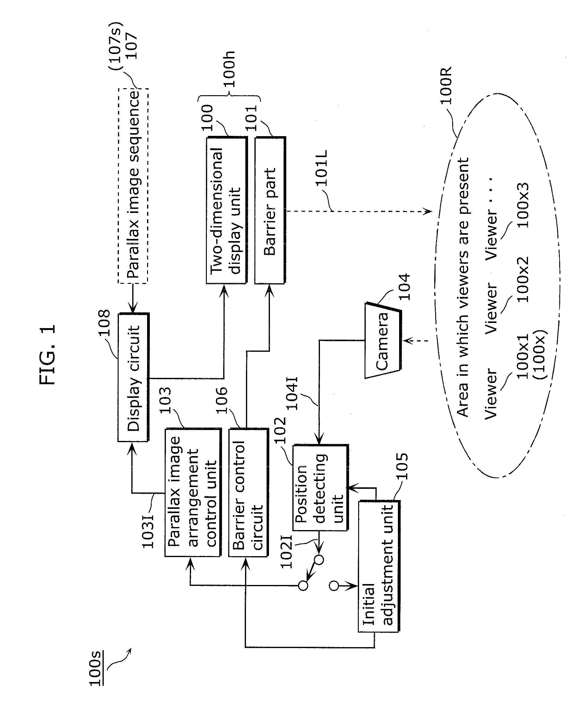
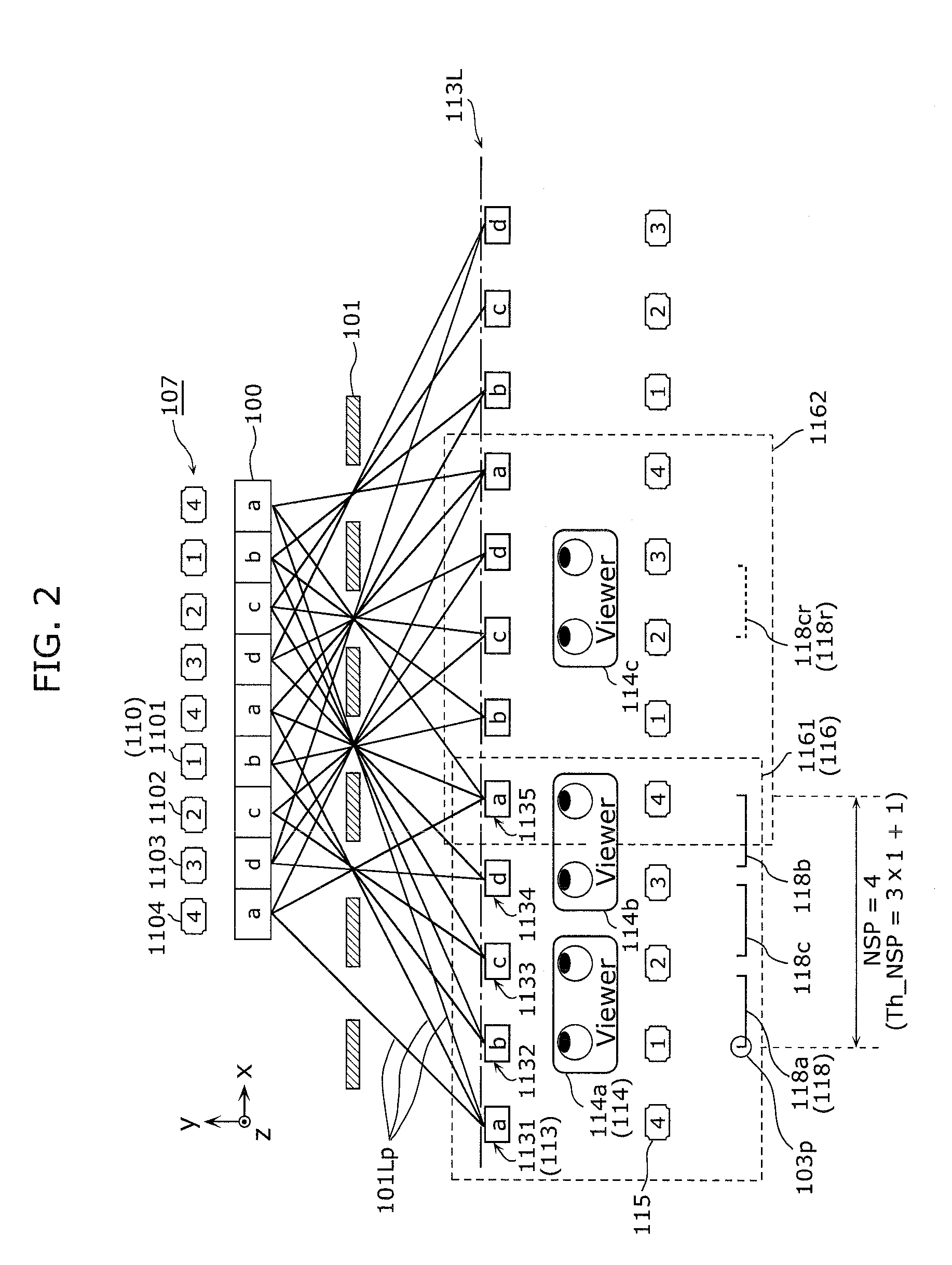
[0091]FIG. 1 shows a configuration of a stereoscopic video display apparatus according to Embodiment 1. Each of FIG. 2 and FIG. 3 shows an example of parallax image arrangement control in the case where the number of viewers is 3. FIG. 4 shows a more general example of parallax image arrangement control in the case where the number of viewers is n. Here, display position intervals PLen between the display positions of the parallax images in sets of parallax images are assumed to be equal to inter-eye distances Leye. FIG. 5 shows a structure of a position detecting unit of a stereoscopic video display apparatus according to Embodimen...

embodiment 2

[0258]Second embodiment describes an example of dividing each of predetermined position intervals between parallax images with reference to FIG. 9 to FIG. 13.

[0259]Specifically, Embodiment 2 describes an apparatus which displays a stereoscopic video by controlling the display positions of the parallax images on a display panel based on the detected head positions of viewers of stereoscopic video using parallax images whose number is obtained according to the number of viewers×n+1 where n denotes the number of position interval segments.

[0260]FIG. 9 shows a configuration of a stereoscopic video display apparatus according to Embodiment 2. Each of FIGS. 10A and 10B shows processing performed by the display position interval control unit 201 which controls the display position intervals of the parallax images. FIG. 11 shows an example of parallax image arrangement control in the case where the number of viewers n is 2, and the number of position interval segments m is 2. FIG. 12 shows ...

embodiment 3

[0357]With reference to FIG. 14 to FIG. 16A and FIG. 16B, Embodiment 3 describes an apparatus which displays a stereoscopic video by generating a parallax image set according to the number of viewers, by firstly preparing only a set of a left-eye image L and a right-eye image R in the set, and then performing interpolation using the left- and right-eye images.

[0358]FIG. 14 shows a structure of a stereoscopic video display apparatus according to Embodiment 3. FIG. 15 shows a structure of the parallax image generating unit 301 inside the stereoscopic video display apparatus according to Embodiment 3. As shown in FIG. 14, the stereoscopic video display apparatus according to Embodiment 3 includes the parallax image generating unit 301 which receives, as inputs, L and R parallax images instead of a plurality of parallax images used in Embodiment 1 generates predetermined parallax images.

[0359]Thus, the parallax image generating unit 301 is also applicable to Embodiment 2. The other stru...


PUM


Abstract

A stereoscopic video display apparatus includes: a two-dimensional display unit which selects, for each of parallax images having a parallax from a reference parallax image, at least one pixel sequence on a panel, and displays each of the parallax images using the selected pixel sequence; a barrier part which divides light from the pixel sequences such that the respective parallax images are displayed at predetermined positions; a position detecting unit which detects the positions of viewers; and a parallax image arrangement control unit which specifies viewing positions possible for the left eyes of the viewers from among the detected viewing positions other than the viewing positions for the right eyes, and cause the two-dimensional display unit to respectively display the parallax images predetermined for the left eyes at the specified positions.

Description

CROSS REFERENCE TO RELATED APPLICATIONS[0001]This is a continuation application of PCT Patent Application No. PCT / JP2011 / 002327 filed on Apr. 21, 2011, designating the United States of America, which is based on and claims priority of Japanese Patent Application No. 2010-098310 filed on Apr. 21, 2010. The entire disclosures of the above-identified applications, including the specifications, drawings and claims are incorporated herein by reference in their entirety.BACKGROUND OF THE INVENTION[0002](1) Field of the Invention[0003]The present invention relates to a stereoscopic video display apparatus which enables viewers to view a stereoscopic video without wearing any special glasses.[0004](2) Description of the Related Art[0005]Apparatuses configured to include parallax barriers or lenticular lenses (spectroscopes) arranged facing viewers of a display apparatus such as a liquid crystal panel, a PDP, and the like have been conventionally known as apparatuses which display stereoscop...

Claims


Application Information

Patent Timeline
IPC IPC(8): H04N13/04G02B30/31
CPCG02B27/2214G02B27/225H04N13/0477H04N13/0447H04N13/0413H04N13/315H04N13/351H04N13/376G02B30/31G02B30/27
Inventor WATANABE, TATSUMI
Owner PANASONIC INTELLECTUAL PROPERTY CORP OF AMERICA
Why Eureka
Try Eureka