Method and system for detecting defects of transparent substrate
- Summary
- Abstract
- Description
- Claims
- Application Information
AI Technical Summary
Benefits of technology
Problems solved by technology
Method used
Image

Examples
first embodiment
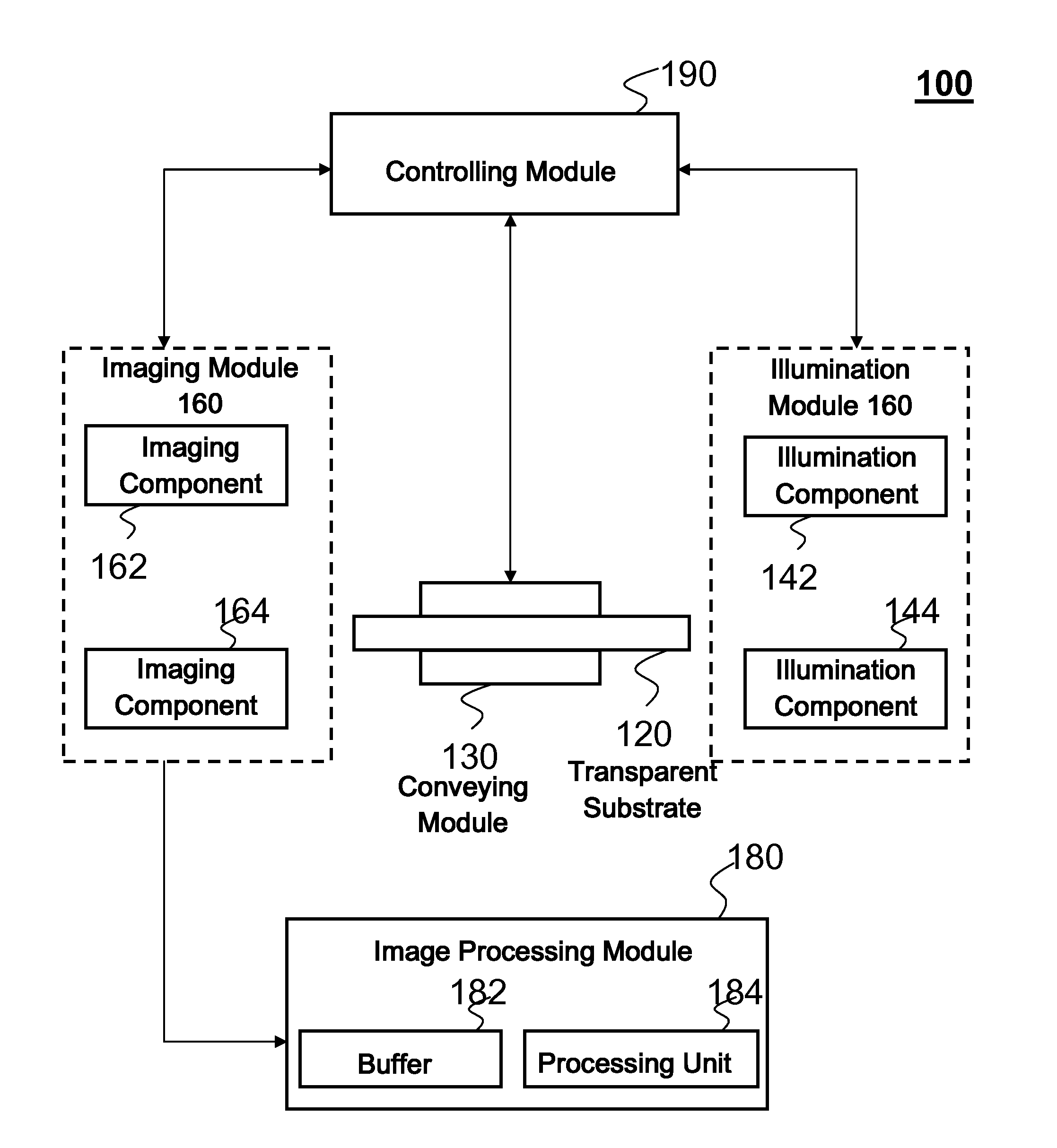
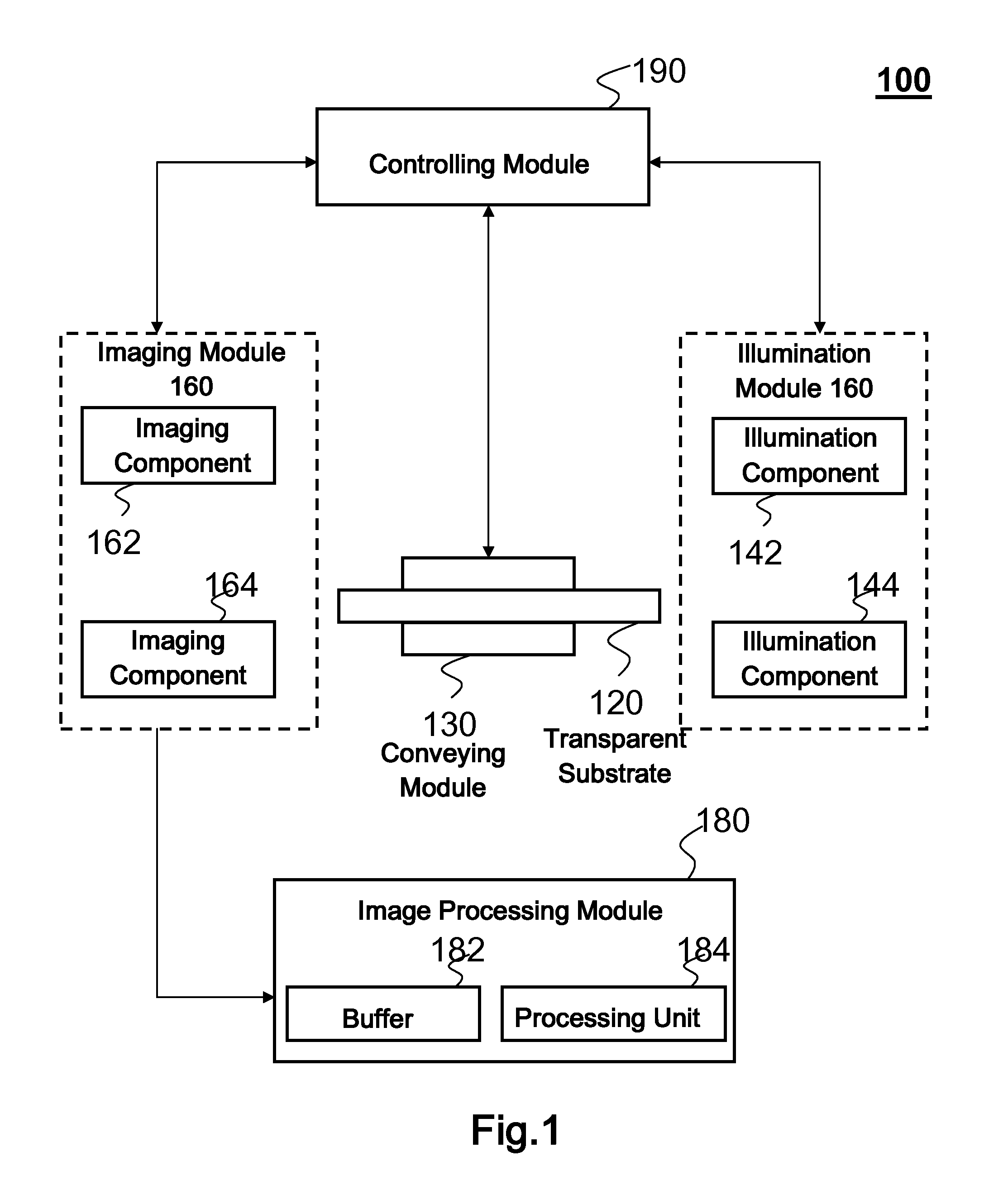
[0022]FIG. 1 shows a system 100 for detecting defects of a transparent substrate 120 according to the present invention. The defect detection system 100 comprises a transport module 130, an illumination module 140, an imaging module 160, an image processing module 180 and a controlling module 190. In order to remove the influence of environment light, the whole system 100 may be covered with a black cover (not shown in FIG. 1).
[0023]In the first embodiment, the transparent substrate 120 may be glass, plastic, or any other transparent material, such as glass ribbon on float line, raw glass panel, glass substrate of photovoltaic module and glass substrate of flat panel display device. The substrate 120 is not limited to the form of a sheet having substantially parallel surfaces, but can be extended to the form of a cylinder curved in a plane vertical to transporting direction of the substrate. Unless otherwise specified, as used therein, the term “two opposite sides of the substrate” ...
third embodiment
[0045]In addition, for example, the detection system of the present invention may use one imaging component 162 and a plurality of (three in the embodiment shown in FIG. 6) illumination components 142, 144, 746. As illustrated in FIG. 6, the illumination components 142 and 746 are located on the same side of the substrate 120 as the imaging component 162, while the illumination component 144 is located on the other side of the substrate 120. Here, the illumination components 142 and 746 provide dark field reflection illumination to the substrate 120 relative to imaging component 162 at different illumination angles, while the illumination component 144 provides bright field transmission illumination to the substrate 120 relative to imaging component 162. The controlling module 190 performs controlling operation so that the illumination component 142 and illumination component 746 may switch on simultaneously or not simultaneously, but either of them is switched on simultaneously wit...
fourth embodiment
[0046]FIG. 7 illustrates a four-channel optical configuration according to the present invention. As shown in FIG. 7, the system 100 includes four detection channels, i.e., a first detection channel, a second detection channel, a third detection channel and a fourth detection channel.
[0047]The first detection channel may include a dichromic mirror 310 placed on one side of the substrate 120 and capable of transmitting a red color light to the substrate 120 and reflecting a blue color light, a dual color illumination component 148 placed on the one side of the substrate 120 and capable of emitting the red color light and the blue color light, and the first imaging component 162 placed on another opposite side of the substrate 120. The dual color illumination component 148 may be a dual color LED. In the first detection channel, the dual color illumination component 148 may emit the red color light to the dichromic mirror 310, the dichromic mirror 310 may transmit through the red colo...
PUM
 Abstract
Description
Claims
Application Information