
Alternator for automobile having washer between housing and outer race of bearing

a technology of outer race and washer, which is applied in the direction of shaft and bearing, rotary bearing, spring/damper, etc., can solve the problems of complicated steps for separating washers from one another, and achieve the effect of easy separation and easy production

Inactive Publication Date: 2012-02-23
DENSO CORP
View PDF7 Cites 21 Cited by
  • Summary
  • Abstract
  • Description
  • Claims
  • Application Information

AI Technical Summary

Benefits of technology

[0013]An object of the present invention is to provide, with due consideration to the drawbacks of the conventional, a generator of an automobile in which a washer is easily produced and stably applies a pressing force to an outer race of a front or rear bearing supported by a housing while being movable along an axial direction of a rotor.
[0016]The washer has the base portion closed along the circumferential direction. Therefore, even when washers are intertwined during the thermal treatment and surface finishing for the washers in mass production, the intertwinement of the washers is not complicated, but the washers can be easily separated from one another. Accordingly, the washer can be easily produced.
[0017]Moreover, because the spring portions are separately located in the washer, spring constants of the spring portions can be independently set such that the washer appropriately applies the pressing force to the outer race of the force receiving bearing. Further, because the washer has many spring portions, the spring constant of each spring portion can be set at a comparatively low value, and the total spring constant of the washer can be maintained at a constant value in the wide range of the displacement of the spring portions deformed along the axial direction. Accordingly, the washer can stably apply the pressing force to the force receiving bearing.

Problems solved by technology

However, this space between the end portions easily causes the intertwinement of washers during the thermal treatment and surface finishing performed after the shaping of the washers in mass production.
Particularly, as the number of washers intertwining one another is increased, the step for separating the washers from one another is complicated, and it is sometimes required to manually separate the intertwining washers from one another.
Further, in case of the single layer wave washer having no open space along the circumferential direction, spring characteristics such as a spring constant are rapidly changed with the deformation of the washer, so that the washer located between the rear bearing and the inner side surface of the side wall of the rear frame cannot stably apply a pressing force to the outer race of the rear bearing.

Method used


Image

  • Alternator for automobile having washer between housing and outer race of bearing
  • Alternator for automobile having washer between housing and outer race of bearing
  • Alternator for automobile having washer between housing and outer race of bearing

Examples


first embodiment

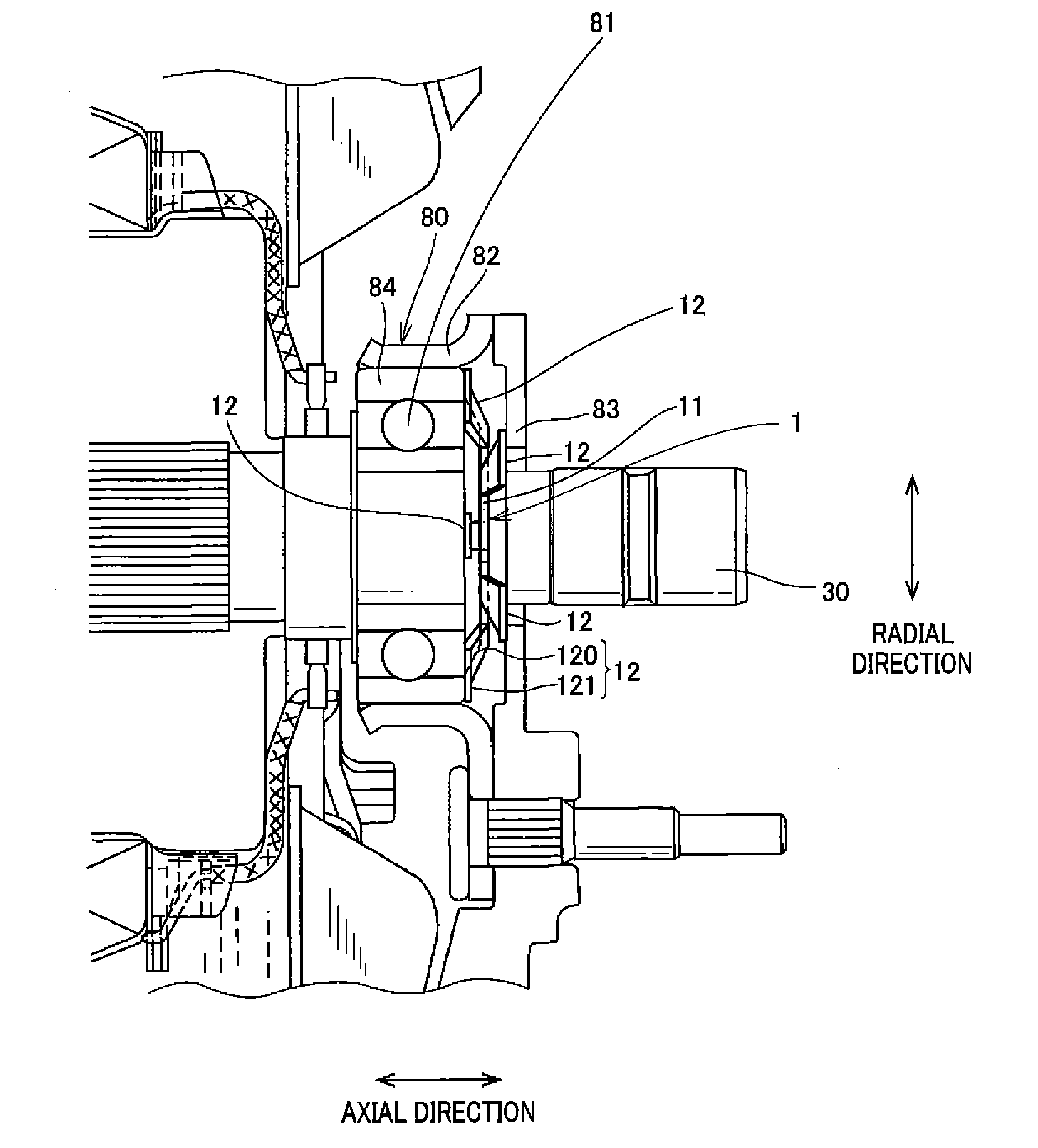
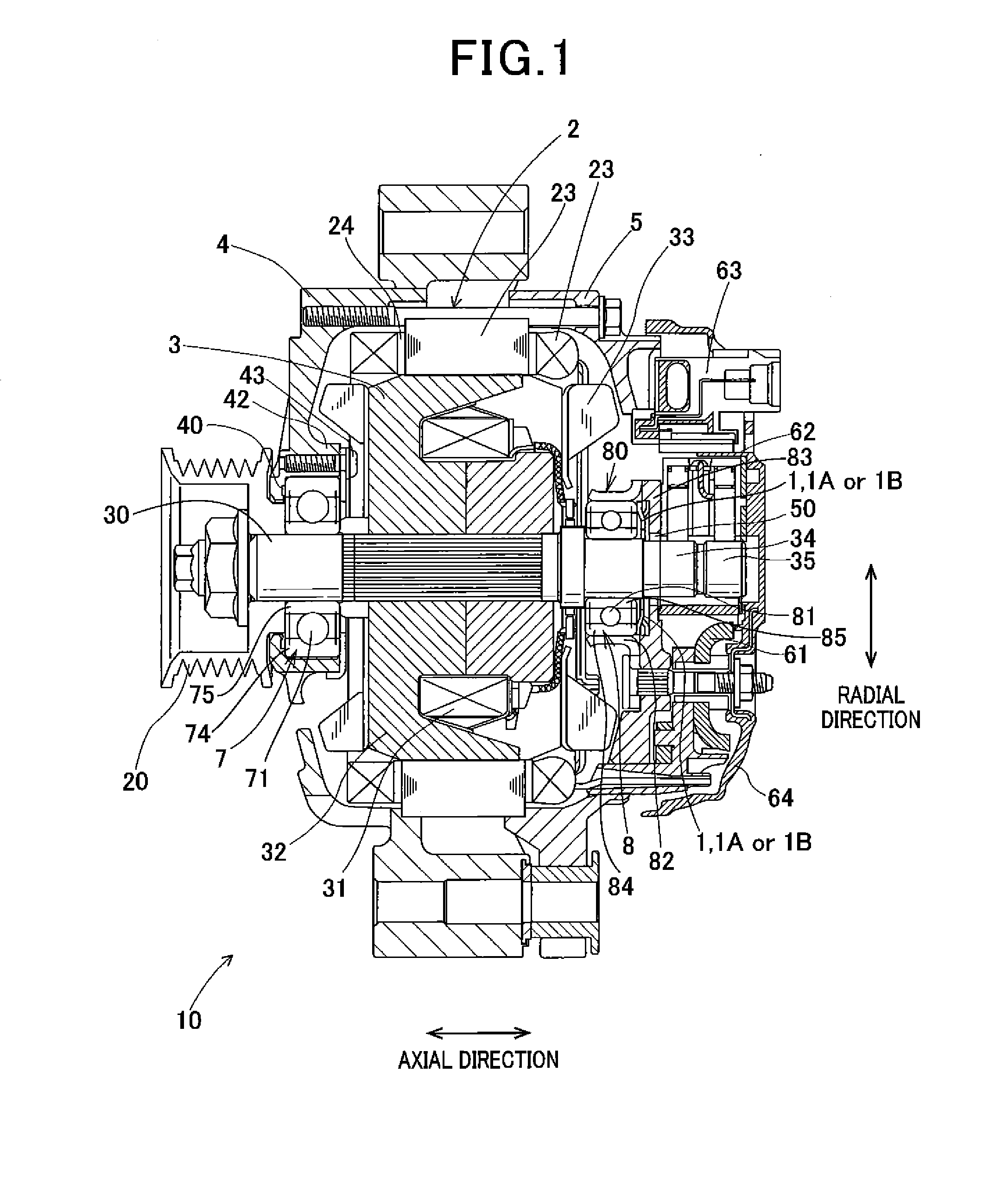
[0028]FIG. 1 is a view, partially in cross section, showing the structure of an alternator 10 of an automobile according to the first embodiment. The alternator 10 is driven by a rotational torque, generated in an engine of the automobile and transmitted through a belt, to charge an accumulator battery mounted on the automobile and to supply electric power to electric consumers mounted on the automobile.

[0029]As shown in FIG. 1, the alternator 10 has a stator 2 formed in a cylindrical shape, a rotor 3, and a housing composed of a drive end frame (hereinafter, called a front frame) 4 and a rear end frame (hereinafter, called a rear frame) 5. Each of the frames 4 and 5 is made of aluminium alloy and is formed in a cup shape. The frames 4 and 5 are attached to each other through the stator 2 such that open spaces of the frames face each other. A rectifier 61, a brush apparatus 62 and a voltage adjusting apparatus 63 are located on the rear side of a rear side wall of the frame 5 and ar...

second embodiment

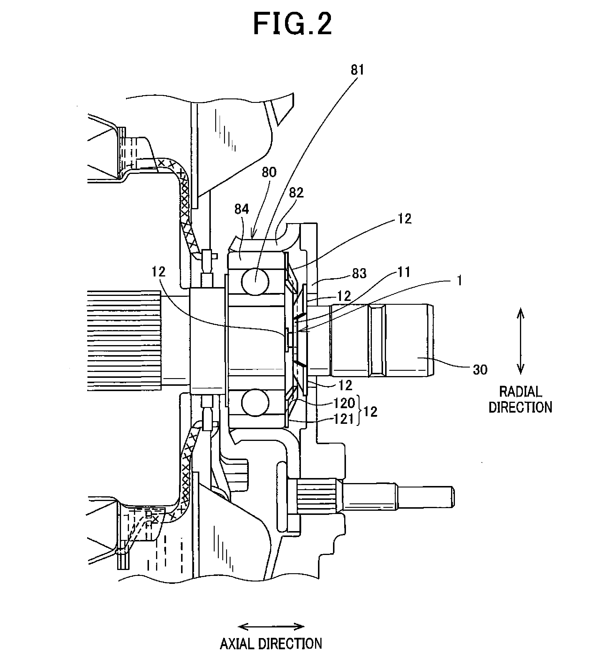
[0052]In this embodiment, a washer 1A integrally formed almost in a double-ring shape is located as the biasing member in a space between the rear bearing 81 and the side wall surface 83 of the rear frame 5 so as to be in contact with both the outer race 84 of the bearing 81 and the side wall surface 83.

[0053]FIG. 4A is a front view of the washer 1A according to the second embodiment, while FIG. 4B is a side view of the washer 1A seen from a direction of an arrow shown in FIG. 4A. As shown in FIG. 4A and FIG. 4B, the washer 1A has the base portion 11 formed flatly and a plurality of spring portions 12A extending from the outer circumferential end of the base portion 11 toward the outside along the radial direction of the base portion 11. The washer 1A has at least three spring portions 12A separately located. For example, the washer 1A has three spring portions 12A arranged at equal intervals along the circumferential direction.

[0054]Each spring portion 12A is composed of a connecti...

third embodiment

[0064]In this embodiment, a washer 1B integrally formed almost in a double-ring shape is located as the biasing member in a space between the rear bearing 81 and the side wall surface 83 of the rear frame 5 so as to be in contact with both the outer race 84 of the bearing 81 and the side wall surface 83.

[0065]FIG. 5A is a front view of the washer 1B according to the third embodiment, while FIG. 5B is a side view of the washer 1B seen from a direction of an arrow shown in FIG. 5A. As shown in FIG. 5A and FIG. 5B, the washer 1B has the ring-shaped base portion 11 and a plurality of spring portions 12B. The shape and size of the washer 1B projected on the plane in which the base portion 11 exists are the same as the projected shape and size of the washer 1A. Each spring portion 12B is composed of a connection portion 124 extending from the base portion 11 in the same plane as that of the base portion 11 in the same manner as the connection portion 122 shown in FIG. 4A, first and second...


PUM


Abstract

An alternator has front and rear bearings, supported by front and rear frames, to rotatably support a shaft of a rotor extending along axial direction. A washer is located between the rear frame and the rear bearing to apply pressing force to the rear bearing slightly movable along axial direction. The washer has a ring-shaped base portion concentrically located with the rear bearing, slanting portions extending from the base portion toward outside of radial direction such that two adjacent slanting portions arranged as each pair along circumferential direction are inclined to different sides of axial direction, and flattened portions extending from respective slanting portions toward outside and being parallel to the base portion. Flattened portions shifted to front side are in contact with the rear bearing, and flattened portions shifted to rear side are in contact with the rear frame.

Description

CROSS-REFERENCE TO RELATED APPLICATION[0001]This application is based upon and claims the benefit of priority of the prior Japanese Patent Application 2010-183079 filed on Aug. 18, 2010, so that the contents of which are incorporated herein by reference.BACKGROUND OF THE INVENTION[0002]1. Field of the Invention[0003]The present invention relates generally to an alternator mounted on an engine of an automobile such as a truck, and more particularly to the alternator in which bearing units of a rotational shaft have improved vibration proofing while creep caused in bearings of the units is suppressed.[0004]2. Description of Related Art[0005]An alternator attached to an engine of an automobile so as to be driven by the engine has a housing which is composed of a front frame and a rear frame. Each frame is formed in a cup shape, open spaces of the frames are faced each other, and the frames are attached to each other through a stator formed in a cylindrical shape so as to fixedly hold t...

Claims


Application Information

Patent Timeline
IPC IPC(8): F16C33/58
CPCF16C25/083
Inventor MASHINO, MIKIOHAMADA, HIROSHI
Owner DENSO CORP
Learn More