System for controlling hydraulic pressure and flow rate of oil in engine and control method thereof

a technology of hydraulic pressure and flow rate, which is applied in the direction of auxilary lubrication, pressure lubrication, lubrication elements, etc., can solve the problems of reducing the life of the engine, reducing the power, and different oil pressures at the oil pump and at the main and head galleries, so as to prevent frictional loss

Inactive Publication Date: 2012-03-01
HYUNDAI MOTOR CO LTD +1
View PDF4 Cites 35 Cited by
  • Summary
  • Abstract
  • Description
  • Claims
  • Application Information

AI Technical Summary

Benefits of technology

[0011]Various aspects of the present invention are directed to provide a system for controlling hydraulic pressure and flow rate of oil in an engine that can prevent frictional loss due to hydraulic pressure and unnecessary consumption of oil, by controlling the opening of a solenoid valve mounted in each channel in accordance with the speed and load of the engine and temperature of the oil to supply oil corresponding to the minimum flow rate required by each gallery, and a control method thereof.
[0018]A system for controlling hydraulic pressure and flow rate of oil in an engine and a control method thereof according to the present invention make it possible to prevent frictional loss due to hydraulic pressure and unnecessary consumption of oil, by controlling the opening of a solenoid valve mounted in each channel in accordance with the speed and load of the engine and temperature of the oil to supply oil corresponding to the minimum flow rate required by each gallery.

Problems solved by technology

The parts in the engine make friction therebetween when generating power and the friction of the parts may reduce the power and decrease the life span of the engine.
However, the oil pressure is different at the oil pump and at the main and head gallery due to hydraulic pressure loss generated through the oil cooler or the oil filter or flow restrictors.
Therefore, it is required to increase very high oil pressure at the oil pump to supply hydraulic pressure corresponding to the desired hydraulic pressure at each gallery, and accordingly, friction increases at the oil pump.
This means oil pumping work should be high and hydraulic pressure loss increase at the oil pump, the oil cooler, and the oil filter and oil consumption is increased by unnecessarily supplying the oil.

Method used


Image

  • System for controlling hydraulic pressure and flow rate of oil in engine and control method thereof
  • System for controlling hydraulic pressure and flow rate of oil in engine and control method thereof
  • System for controlling hydraulic pressure and flow rate of oil in engine and control method thereof

Examples


Embodiment Construction

[0024]Reference will now be made in detail to various embodiments of the present invention(s), examples of which are illustrated in the accompanying drawings and described below. While the invention(s) will be described in conjunction with exemplary embodiments, it will be understood that present description is not intended to limit the invention(s) to those exemplary embodiments. On the contrary, the invention(s) is / are intended to cover not only the exemplary embodiments, but also various alternatives, modifications, equivalents and other embodiments, which may be included within the spirit and scope of the invention as defined by the appended claims.

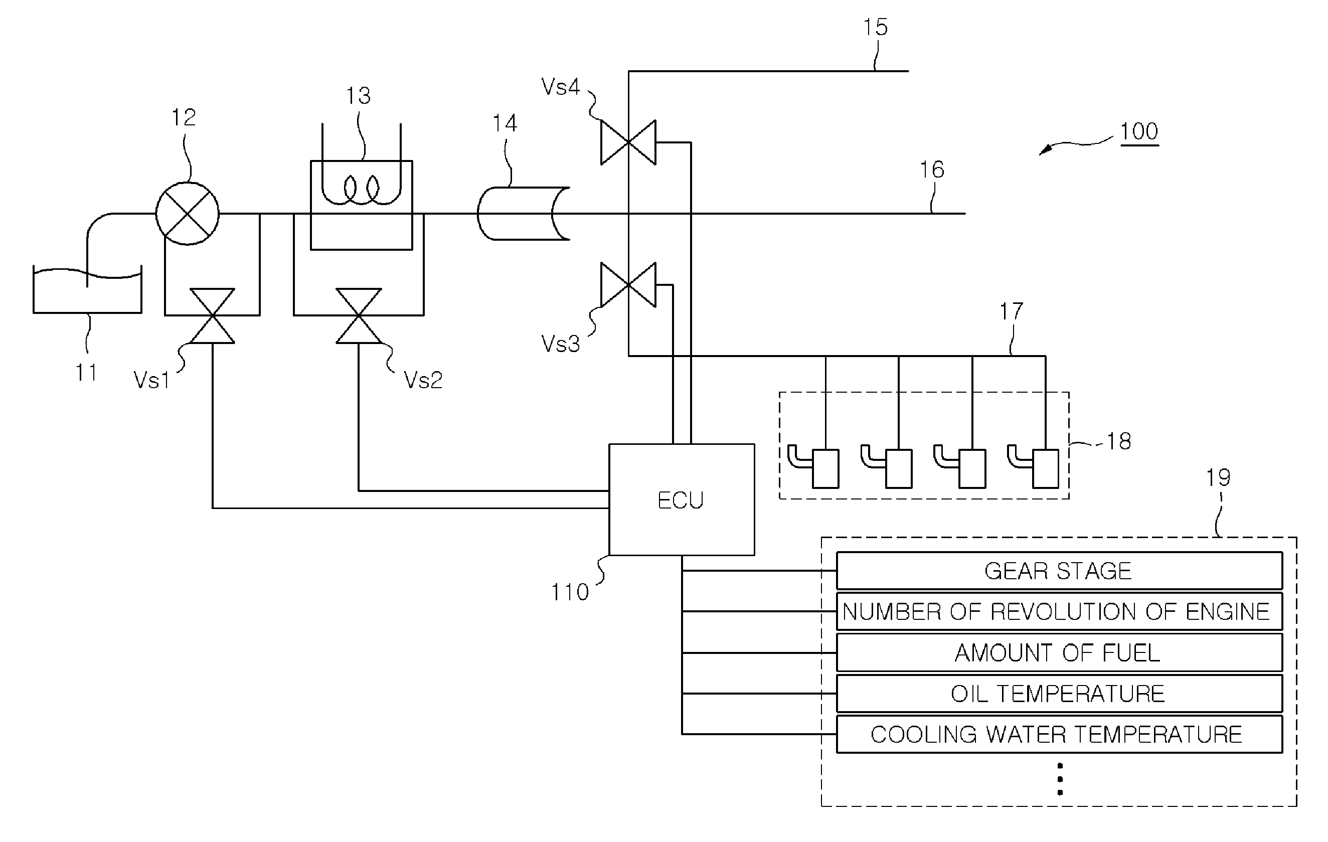
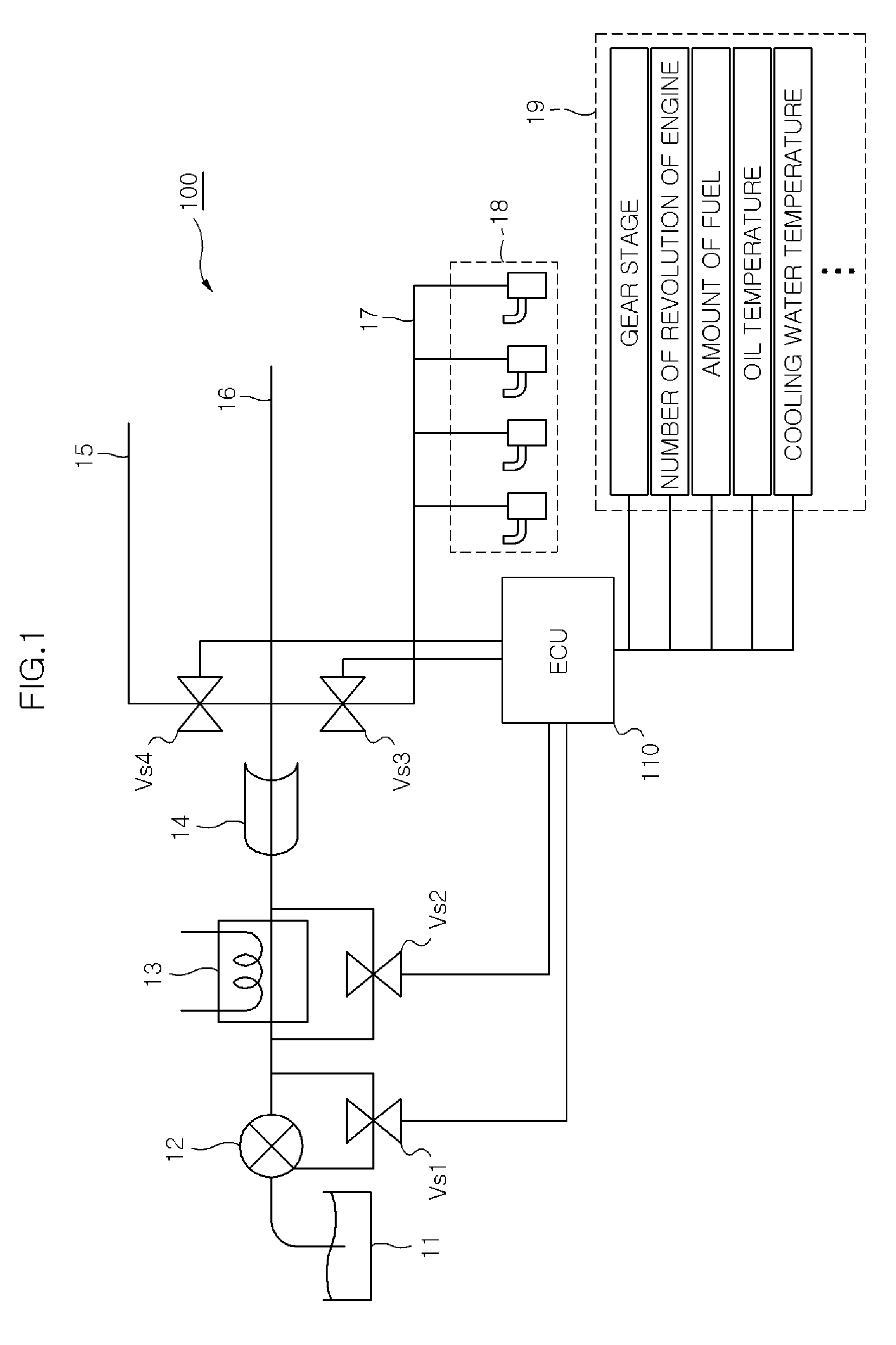
[0025]Referring to FIG. 1, in a system for supplying oil into the engine, as the engine starts, an oil pump 12 pumps up oil from an oil pan 11 connected with the inlet and discharges the oil through the outlet. The oil is sent under predetermined pressure to an oil cooler 13 connected with the outlet of oil pump 12 and cooled through ...


PUM


Abstract

A system for controlling hydraulic pressure and flow rate of oil in an engine, may include a first solenoid valve disposed in a channel connecting an inlet and an outlet of an oil pump supplying oil from an oil pan to the engine, and an electronic controller controlling the first solenoid valve on the basis of number of revolution of the engine, load of the engine, and temperature of the oil.

Description

CROSS-REFERENCE TO RELATED APPLICATIONS[0001]The present application claims priority to Korean Patent Application Number 10-2010-0084694 filed Aug. 31, 2010, the entire contents of which application is incorporated herein for all purposes by this reference.BACKGROUND OF THE INVENTION[0002]1. Field of the Invention[0003]The present invention relates to a system for controlling hydraulic pressure and flow rate of oil in an engine and a control method thereof, and more particularly, to a system for controlling hydraulic pressure and flow rate of oil in an engine that can prevent frictional loss due to hydraulic pressure and unnecessary consumption of oil, by controlling the opening of a solenoid valve mounted in each channel in accordance with the speed and load of the engine and temperature of the oil to supply oil corresponding to the minimum flow rate required by each gallery, and a control method thereof.[0004]2. Description of Related Art[0005]In general, in vehicles, fuel and air...

Claims


Application Information

Patent Timeline
Patent Type & Authority Applications(United States)
IPC IPC(8): F01M1/02
CPCF01M1/08F01M5/005F01M1/16
Inventor CHUNG, YOUNGROCK
Owner HYUNDAI MOTOR CO LTD
Why Eureka
Try Eureka