
Cartridge with a plurality of c-shaped ligature clips

a technology of ligature clips and cartridges, which is applied in the field of cartridges with a plurality of c-shaped ligature clips, can solve the problems of substantial feeding force, accumulation of production tolerances of ligature clips, and difficulty in arranging a cartridge for ligature clips inside the available spa

Active Publication Date: 2012-03-01
AESCULAP AG
View PDF3 Cites 116 Cited by
  • Summary
  • Abstract
  • Description
  • Claims
  • Application Information

AI Technical Summary

Benefits of technology

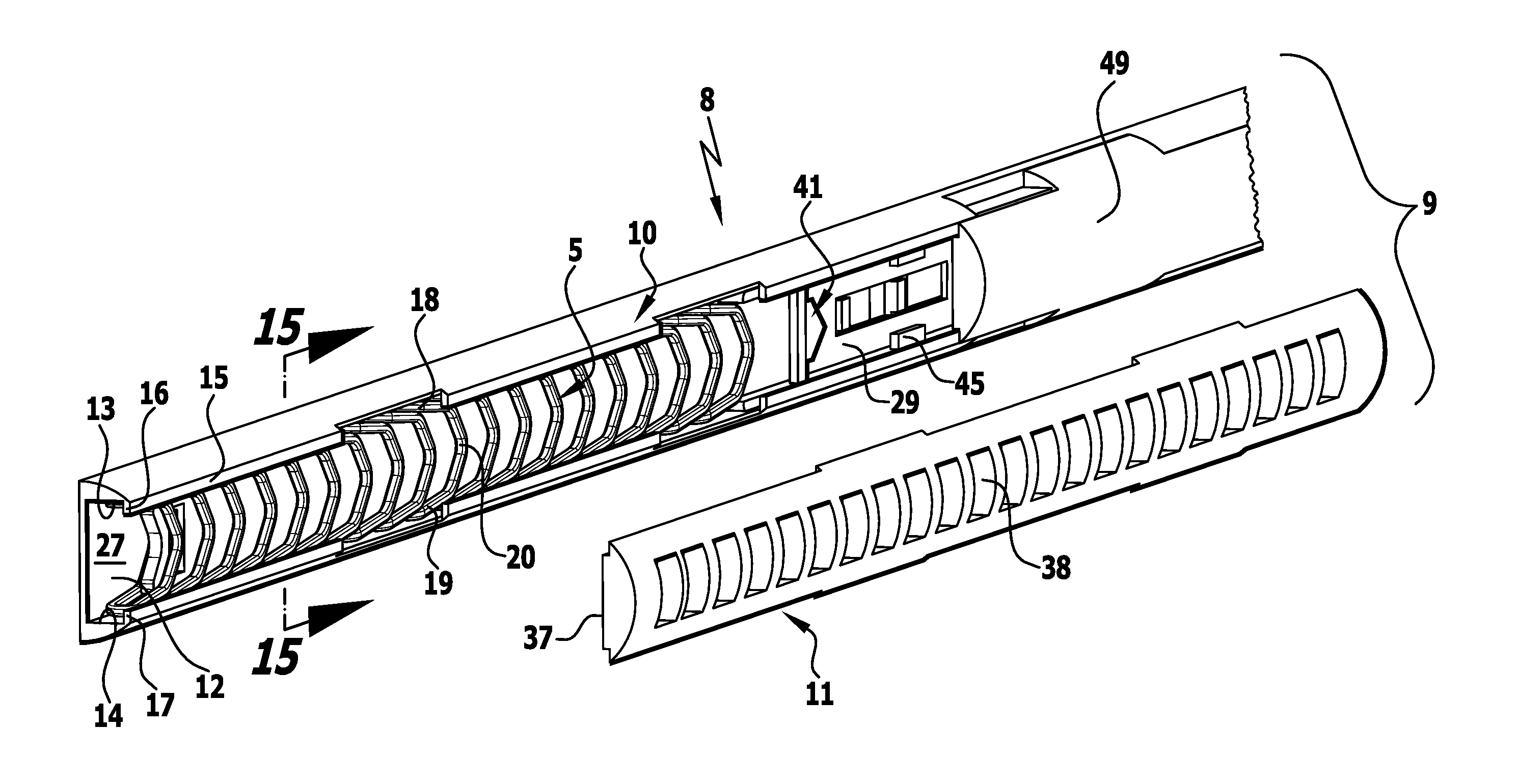
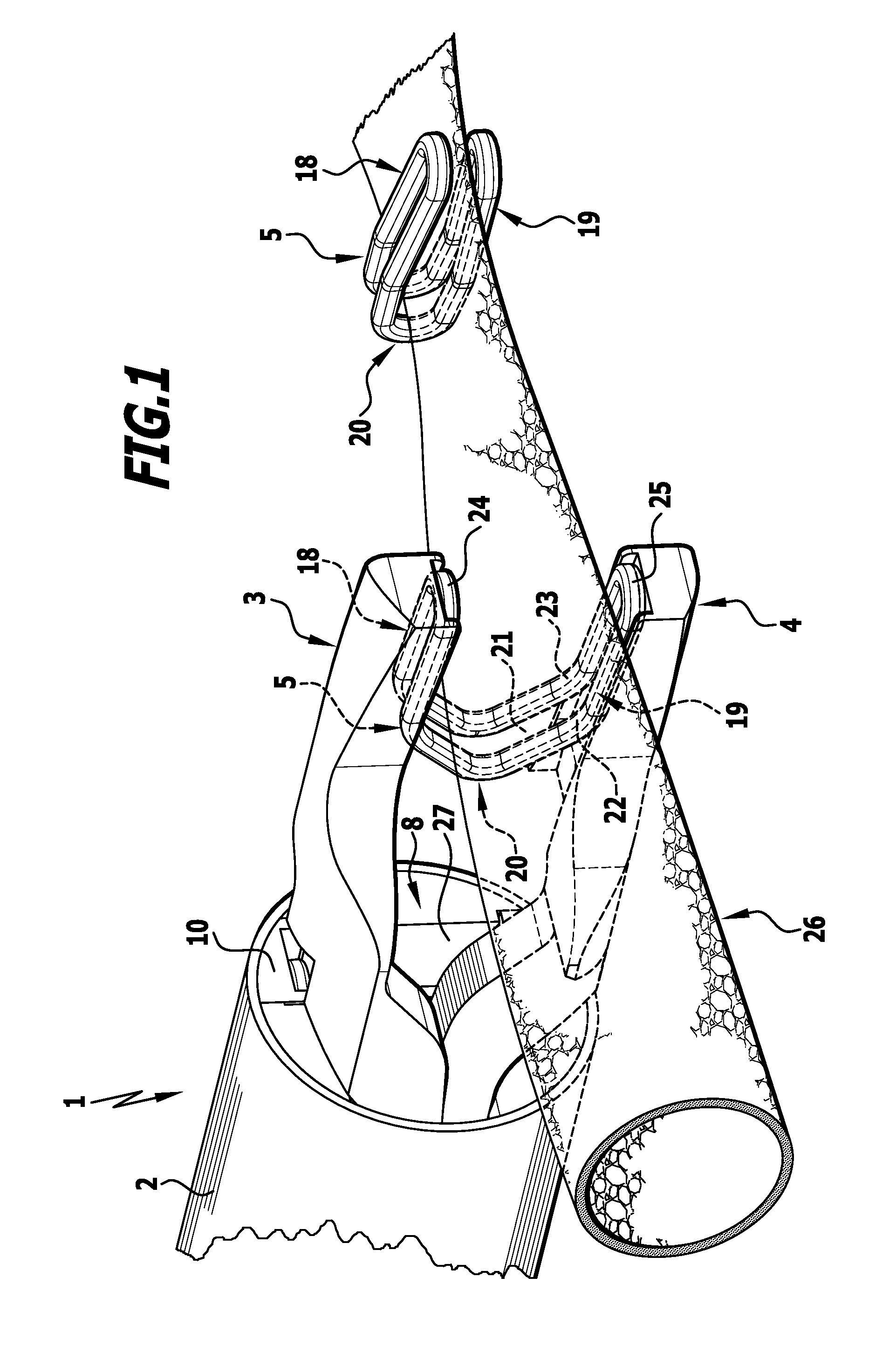
[0012]Because of the arrangement of the transport element in the space between the adjacent sections of the ligature clips, this space is used for the transport element which is supported in this space so that it can be slid forward and back in relation to the housing surrounding the ligature clips. In this case, the transport element and the ligature clips guide one another, the ligature clips prevent the transport element from buckling, since the ligature clips abut against the housing on the outside, while conversely the ligature clips are protected from tilting by the transport element, which runs on the inside of the ligature clips and passes therethrough in the longitudinal direction. A substantial advantage is the space saving, since no further transport element has to be arranged next to the ligature clips. This is accommodated inside the ligature clips and does not require any additional space and, moreover, the transport element is located in the plane of the ligature clips and in the centre thereof, so that no lateral bending moments act on the transport element that could lead to a deformation.
[0047]The guidance between the transport element and the ligature clips is of particular importance in the case of the ligature clip furthest forward. Namely, according to a preferred embodiment it can be provided that in the case of the ligature clip furthest forward in the row, the transport element projects into the space between the sections. This ensures that the ligature clip furthest forward is also still provided with guidance when leaving the cartridge and thereafter by the pushed forward transport element, in particular also when the feed path does not run exactly rectilinearly between the clamping jaws adjoining the cartridge, but instead has a curved course. A transport element configured as a flat strip can follow this curved course and thus also guide the ligature clip along this curved feed path.

Problems solved by technology

However, this requires that the consecutive ligature clips are supported against one another and a disadvantage with these designs is that production tolerances of the ligature clips accumulate and that substantial feeding forces must be transmitted by means of the feed element and in particular the ligature clips lying at the back (DE 695 25 083 T2).
It is thus extraordinarily difficult to arrange a cartridge for ligature clips inside the available space and, moreover, the at least one transport element necessary for advancing the ligature clips.

Method used


Image

  • Cartridge with a plurality of c-shaped ligature clips
  • Cartridge with a plurality of c-shaped ligature clips
  • Cartridge with a plurality of c-shaped ligature clips

Examples


Embodiment Construction

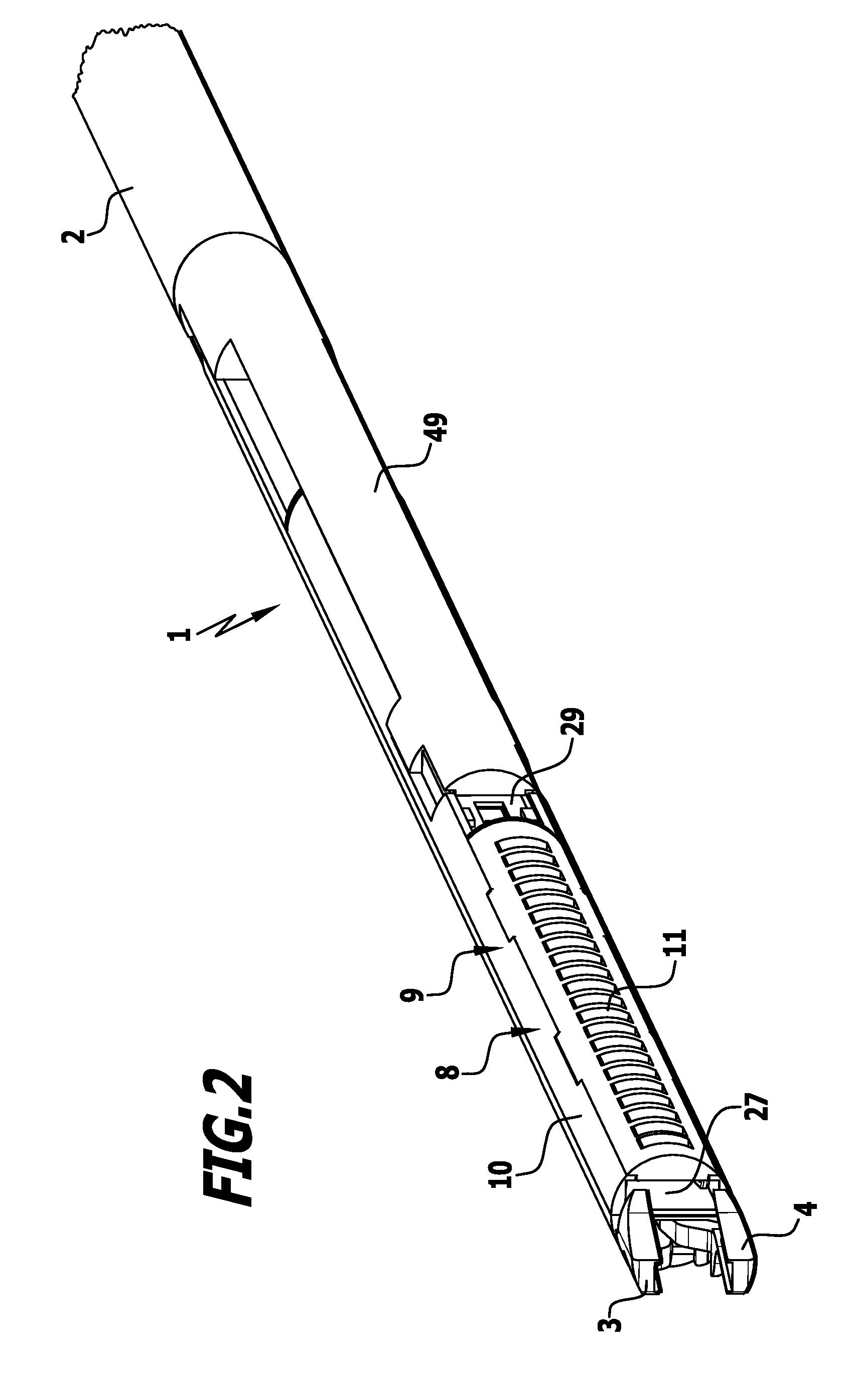
[0081]The placement instrument 1 shown in the drawing comprises an elongated tubular barrel 2 bearing two clamping jaws 3, 4 at its distal end, which are movable relative to one another transversely to the longitudinal direction of the barrel 2, so that a ligature clip 5 inserted between the clamping jaws 3, 4 can thus be deformed from an open position into a closed position. The drive of the clamping jaws 3, 4 is a conventional drive, which is not specially shown in the drawing, and this drive is activated by a transmission member, which passes through the barrel 2 in the longitudinal direction and can be moved by an actuating element, e.g. a pivoting lever, at the proximal end of the barrel 2 in a handle.

[0082]The tubular barrel can have a circular cross-section, but the cross-section of the barrel 2 is reduced in a section 6 directly adjoining the clamping jaws 3, 4, e.g. the barrel 2 still has the cross-section of a semicircle or the cross-section of a sector there, so that next...


PUM


Abstract

In order to simplify the structure of the cartridge and reduce the structural size in a cartridge with a plurality of C-shaped ligature clips, with a housing accommodating ligature clips arranged in a row one behind the other and parallel to one another, with a transport element, which can be slid forward and back relative to the housing in the direction of the row and which when sliding forward and back relative to the housing causes at least one ligature clip to advance towards a discharge end of the cartridge, it is proposed that the ligature clips each have two legs connected by means of a bridge section and are divided by a longitudinal slit into two adjacent sections, which are connected to one another in the region of the free ends of the legs, and that the transport element passes through the ligature clips arranged in a row in the space between the two adjacent sections of the ligature clips.

Description

[0001]This application is a continuation of international application number PCT / EP2010 / 054824 filed on Apr. 13, 2010 and claims the benefit of German application number 10 2009 018 820.7 filed on Apr. 24, 2009.[0002]The present disclosure relates to the subject matter disclosed in international application number PCT / EP2010 / 054824 of Apr. 13, 2010 and German application number 10 2009 018 820.7 of Apr. 24, 2009, which are incorporated herein by reference in their entirety and for all purposes.BACKGROUND OF THE INVENTION[0003]The invention relates to a cartridge with a plurality of C-shaped ligature clips, with a housing accommodating ligature clips arranged in a row one behind the other and parallel to one another, with a transport element, which can be slid forward and back relative to the housing in the direction of the row and which when sliding forward and back relative to the housing causes at least one ligature clip to advance towards a discharge end of the cartridge.[0004]Ca...

Claims


Application Information

Patent Timeline
IPC IPC(8): B65D85/24
CPCA61B17/1285A61B17/1222
Inventor DISCH, ALEXANDERMAYENBERGER, RUPERT
Owner AESCULAP AG
Learn More