Rotor for an electrical machine

a technology of electrical machines and rotors, which is applied in the direction of dynamo-electric machines, electrical apparatus, magnetic circuits, etc., can solve the problems of unsuitable adhesives, unsuitable adhesives, and unsuitable adhesives in atmospheric moisture, so as to reduce shearing strength, avoid excessive strain and fracture of magnets, and transfer good radial stresses

Active Publication Date: 2012-03-01
DYSON TECH LTD
View PDF10 Cites 21 Cited by
  • Summary
  • Abstract
  • Description
  • Claims
  • Application Information

AI Technical Summary

Benefits of technology

[0016]As the rotor rotates, radial forces stress the magnet. At relatively high rotor speeds, these stresses may cause the magnet to fracture and break apart. In order to prevent this, the rotor core assembly may include a sleeve that surrounds the magnet and the end caps. The sleeve may form a clearance fit with the magnet and an interference fit with each of the end caps. An adhesive is then located in the clearance between the magnet and the sleeve. In forming an interference fit with the sleeve, the end caps act to align and radially constrain the sleeve relative to the shaft. The adhesive acts to transfer radial stresses from the magnet to the sleeve. Accordingly, excessive strain and fracture of the magnet may be avoided.
[0017]The adhesive located between the magnet and the sleeve may be different to that located between the magnet and the shaft and / or between magnet and the end caps. For example, an impregnation adhesive may be used between the magnet and the sleeve. An impregnation adhesive has the advantage of penetrating and filling the various voids in the surfaces of the magnet and the sleeve so as to ensure good transfer of radial stresses from the magnet to the sleeve. However, an impregnation adhesive may be unsuitable for securing the magnet to the shaft (e.g. due to reduced shearing strength) or for securing the magnet to the end caps (e.g. due to a lower viscosity).

Problems solved by technology

In particular, the end cap may be secured to the magnet using an adhesive that is unsuitable for securing the magnet to the shaft.
However, owing to the time required to insert the shaft into the bore of the magnet, an adhesive that cures quickly in atmospheric moisture is unlikely to be suitable for securing the magnet to the shaft.

Method used


Image

  • Rotor for an electrical machine
  • Rotor for an electrical machine
  • Rotor for an electrical machine

Examples


Embodiment Construction

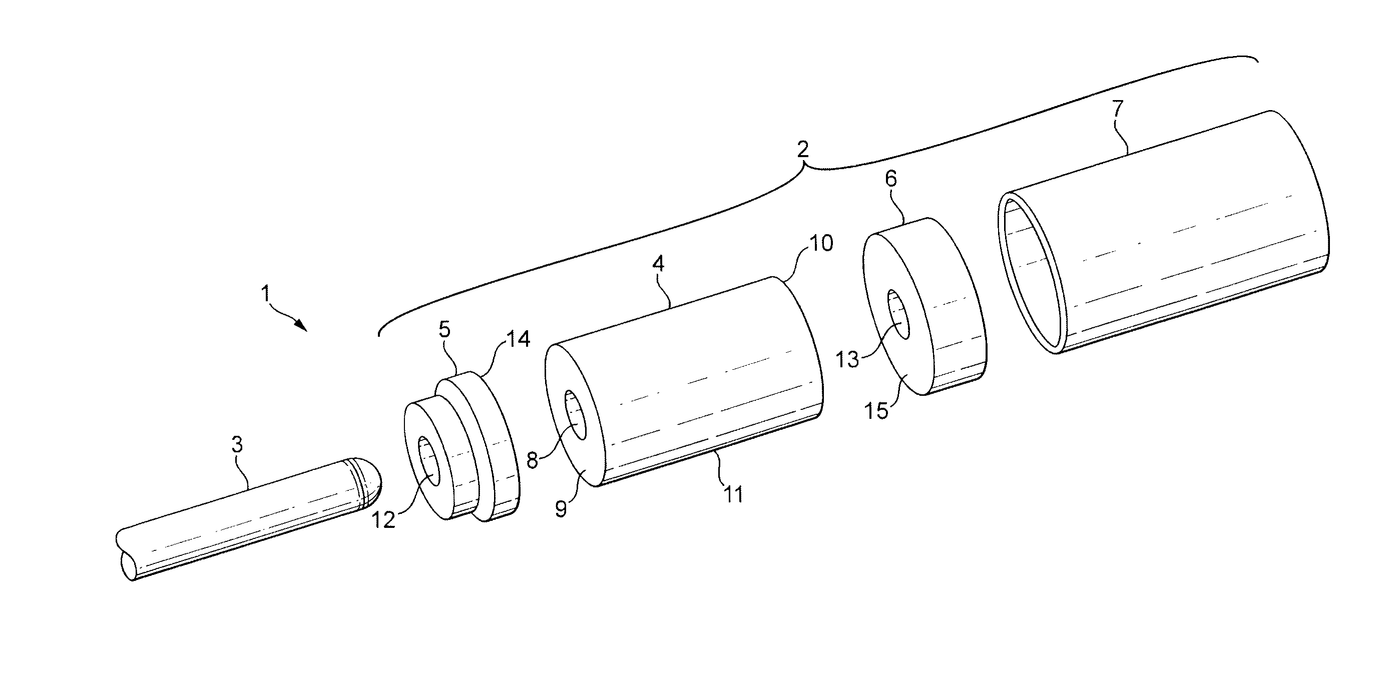
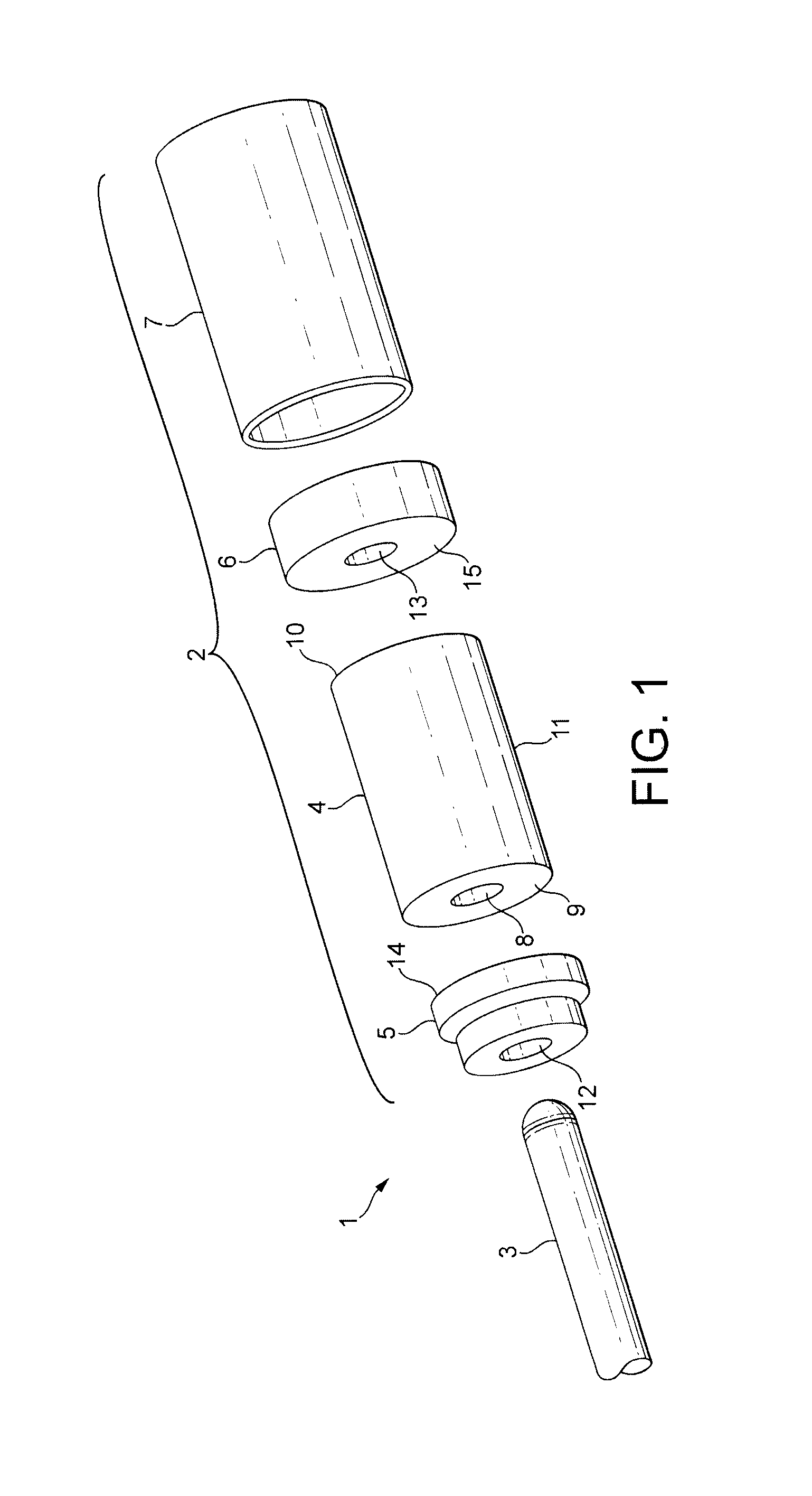
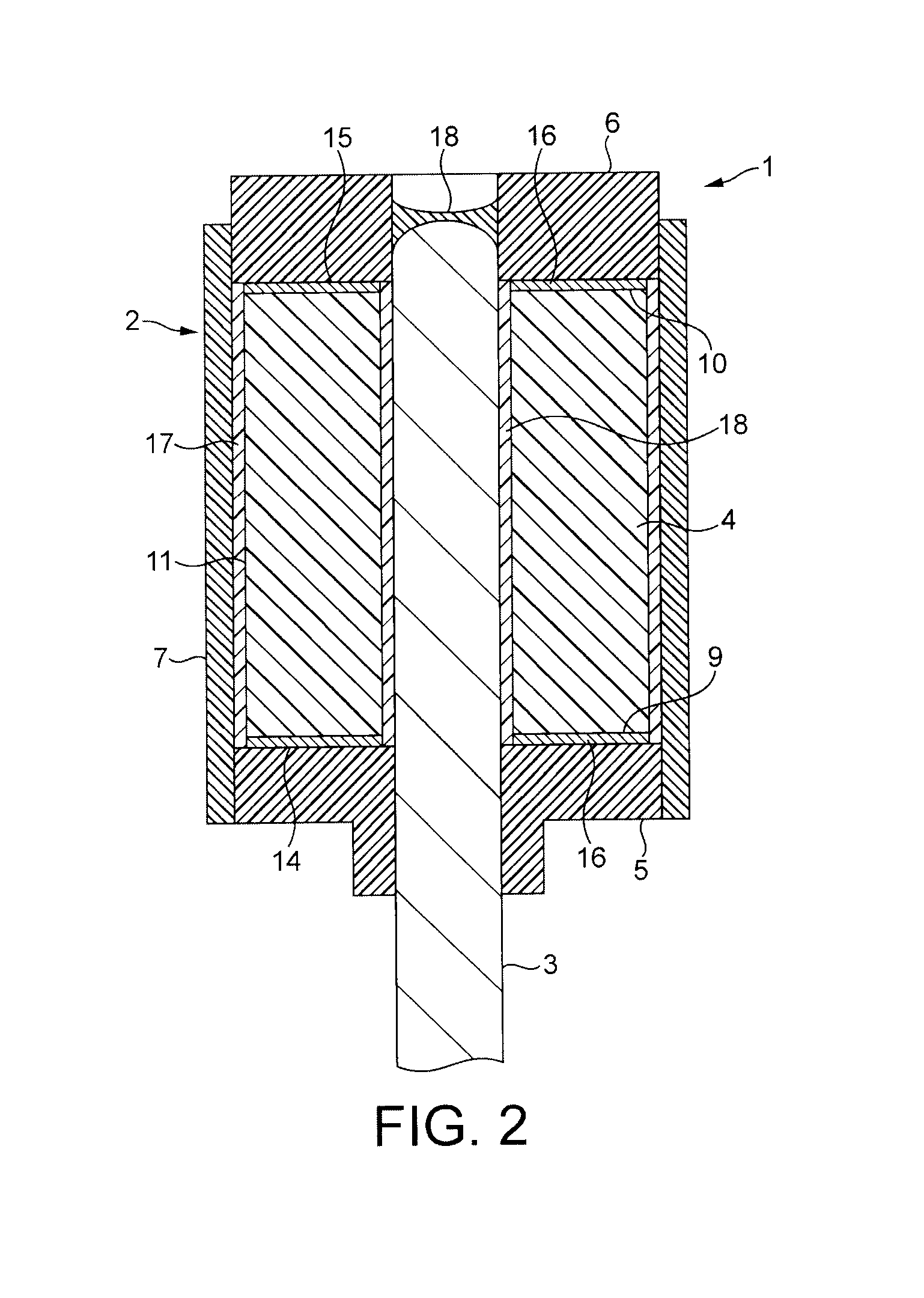
[0032]The rotor 1 of FIGS. 1 and 2 comprises a rotor core assembly 2 secured to a shaft 3.

[0033]The rotor core assembly 2 comprises a permanent magnet 4, a first end cap 5, a second end cap 6, and a sleeve 7.

[0034]The magnet 4 is cylindrical in shape and has a central bore 8 that extends through the magnet 4 from a first end 9 to a second end 10. The bore 8 is sized such that the shaft 3 forms a clearance fit with the magnet 4 when inserted into the bore 8.

[0035]Each end cap 5,6 is made of plastic and has a bore 12,13 formed therethrough. The bore 12,13 in each end cap 5,6 is sized such that the shaft 3 forms an interference fit with the end cap 5,6 when inserted into the bore 12,13. The bore 12,13 in each end cap 5,6 is thus smaller than the bore 8 in the magnet 4. Each end cap 5,6 has a mating face 14,15 that is secured to an end 9,10 of the magnet 4 by an adhesive 16. The end caps 5,6 are secured to the magnet 4 such that the outer diameter of the magnet 4 is aligned concentrical...


PUM

PropertyMeasurementUnit
outer diameteraaaaaaaaaa
inner diameteraaaaaaaaaa
adhesiveaaaaaaaaaa

Abstract

A rotor that includes a rotor core assembly secured to a shaft. The rotor core assembly includes a magnet and an end cap secured to an end of the magnet. Each of the magnet and the end cap has a bore into which the shaft extends. The end cap forms an interference fit with the shaft. The magnet forms a clearance fit with the shaft and an adhesive is located in the clearance between the magnet and the shaft. Additionally, a method of manufacturing the rotor. The method includes inserting the shaft into the bore of the end cap. An adhesive is then introduced into the bore of the magnet and the shaft is inserted into the bore of the magnet so as to cause adhesive to be drawn into the clearance defined between the magnet and the shaft.

Description

REFERENCE TO RELATED APPLICATIONS[0001]This application claims the priorities of United Kingdom Application No. 1014074.7, filed Aug. 24, 2010, and United Kingdom Application No. 1100987.5, filed Jan. 20, 2011, the entire contents of which are incorporated herein by reference.FIELD OF THE INVENTION[0002]The present invention relates to a rotor for an electrical machine.BACKGROUND OF THE INVENTION[0003]The rotor of an electrical machine typically comprises a rotor core secured to a shaft. The rotor core may comprise a magnet having a bore through which the shaft is received. Most magnets are relatively brittle and will fracture if subjected to excessive tensile stress. Consequently, rather than press fitting the magnet on to the shaft, the magnet is generally adhered to the shaft.[0004]The magnet may be adhered to the shaft by applying a bead of adhesive to the shaft and then inserting the shaft into the bore of the magnet. During insertion, the shaft may be rotated relative to the m...

Claims


Application Information

Patent Timeline
Patent Type & Authority Applications(United States)
IPC IPC(8): H02K1/28H02K5/02
CPCH02K1/2733Y10T29/49012H02K1/28H02K15/03H02K15/12H02K1/27
Inventor IONS, DAVID
Owner DYSON TECH LTD
Why Eureka
Try Eureka