Light module

a light module and light technology, applied in the direction of fixed installation, lighting and heating equipment, coupling device connection, etc., can solve the problems of requiring a significant amount of time and space for wiring the circuit board with multiple wires, and unable to effectively package the final lighting system

Active Publication Date: 2012-03-01
TYCO ELECTRONICS NETHERLAND BV +1
View PDF8 Cites 58 Cited by
  • Summary
  • Abstract
  • Description
  • Claims
  • Application Information

AI Technical Summary

Problems solved by technology

Purchasing the various components from different sources proves to make integration into a functioning system difficult.
This non-integrated approach does not allow the ability to effectively package the final lighting system in a lighting fixture efficiently.
Wiring the circuit board with multiple wires generally requires a significant amount of time and space.
In fixtures where space is limited, the wires may require additional time to connect.
Additionally, having multiple wires to connect requires multiple terminations, increasing the time required to connect the LE

Method used


Image

  • Light module
  • Light module
  • Light module

Examples


Embodiment Construction

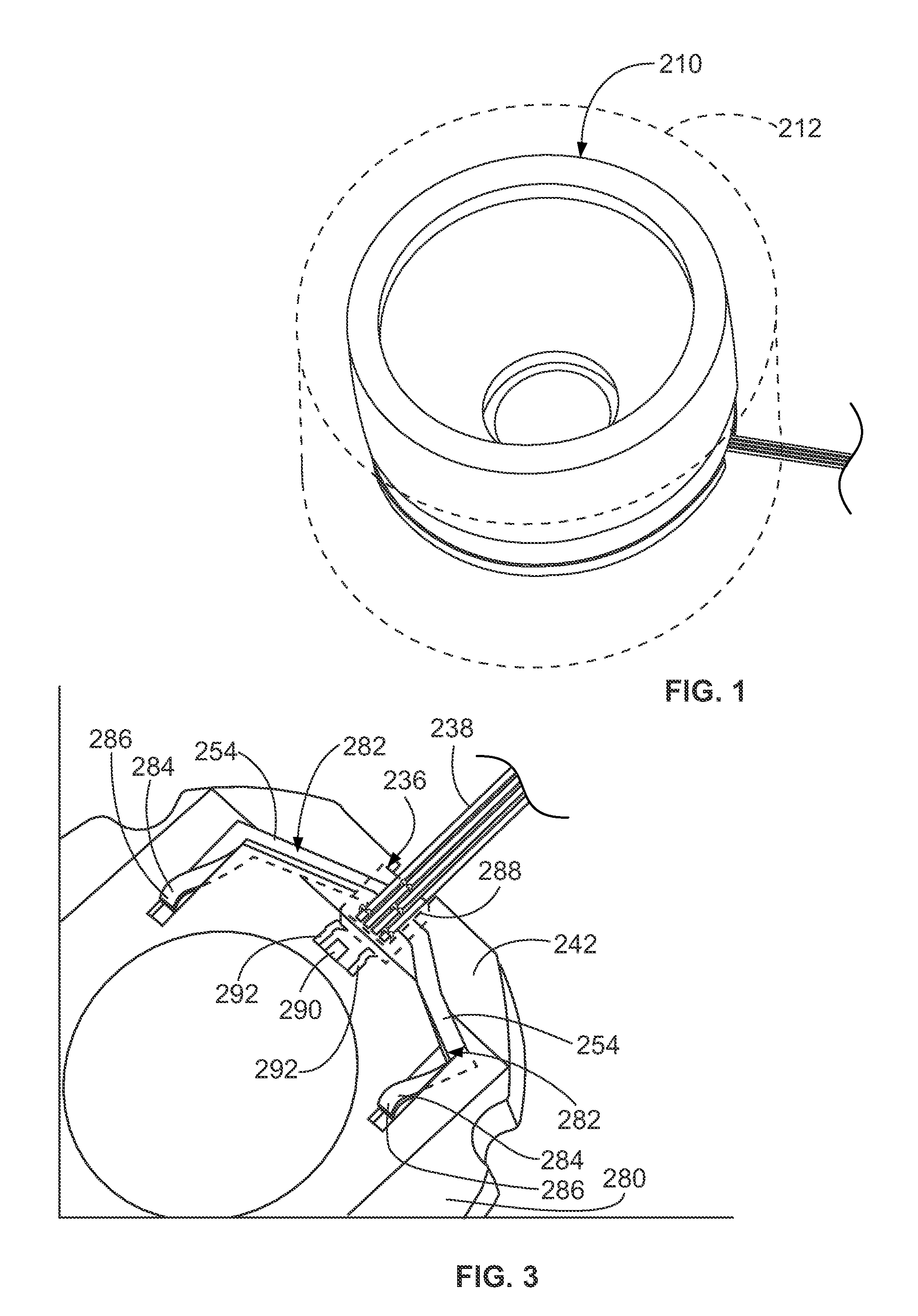
[0023]FIG. 1 illustrates a light module 210 for use in a device 212 (represented schematically in FIG. 1). The light module 210 generates light for the device 212. The device 212 may be any type of lighting device, such as a light fixture. In exemplary embodiment, the device 212 may be a can light fixture, however, the light module 210 may be used with other types of lighting devices in alternative embodiments.

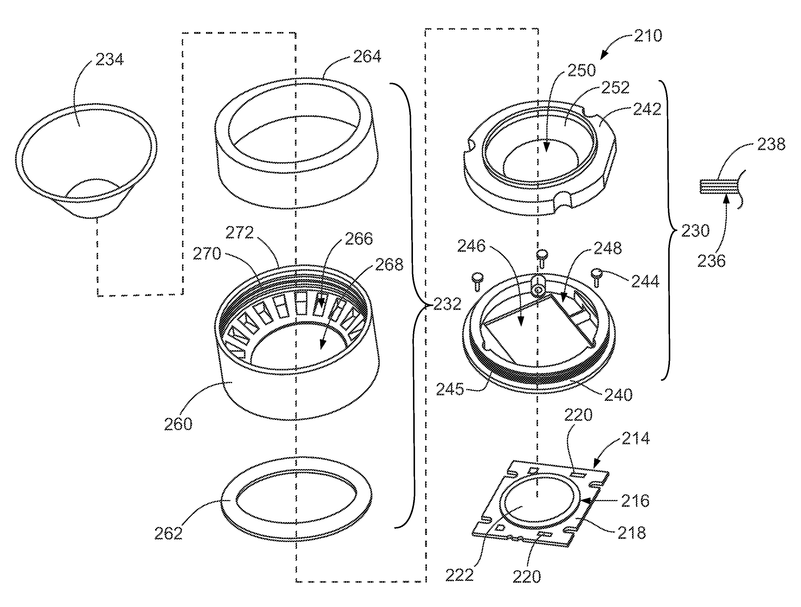
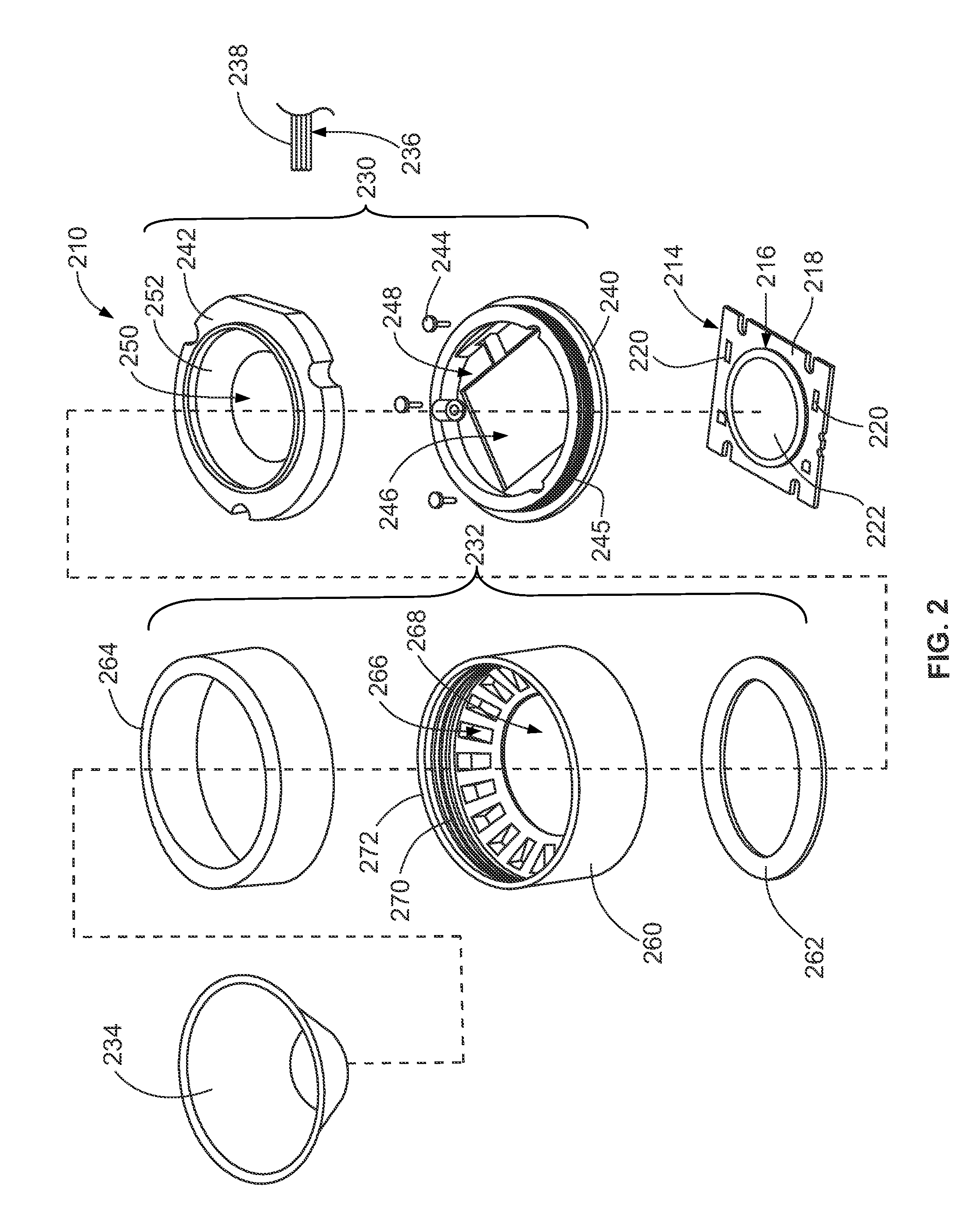
[0024]FIG. 2 is an exploded view of the light module 210. The light module 210 includes a light engine 214 that includes an LED package 216. The LED package 216 has a substrate 218 having a plurality of power terminals 220 on a surface thereof as well as a diode 222 on the surface that is configured to emit light therefrom when the light engine 214 is powered. The diode 222 is a semiconductor in an exemplary embodiment.

[0025]The light module 210 includes a base ring assembly 230 that holds the light engine 214. The light module 210 includes a top cover assembly 232 that is con...


PUM


Abstract

A light module includes a light engine that has an LED package having power terminals. A base ring assembly holds the light engine. The base ring assembly has a base ring configured to be mounted to a supporting structure. The base ring has a securing feature. The base ring assembly has a contact holder that holds power contacts. The power contacts are spring biased against the power terminals to create a separable power connection with the power terminals. A top cover assembly is coupled to the base ring. The top cover assembly has a collar surrounding the base ring. The top cover assembly has a securing feature that engages the securing feature of the base ring to couple the collar to the base ring. The collar has a cavity and the optical component is received in the cavity. The optical component is positioned to receive light from the LED package and the optical component is configured to emit the light generated by the LED package.

Description

BACKGROUND OF THE INVENTION[0001]The subject matter herein relates generally to solid state lighting systems and, more particularly, to a light emitting diode (LED) light module.[0002]Solid-state light lighting systems use solid state light sources, such as light emitting diodes (LEDs), and are being used to replace other lighting systems that use other types of light sources, such as incandescent or fluorescent lamps. The solid-state light sources offer advantages over the lamps, such as rapid turn-on, rapid cycling (on-off-on) times, long useful life span, low power consumption, narrow emitted light bandwidths that eliminate the need for color filters to provide desired colors, and so on.[0003]Solid-state lighting systems typically include different components that are assembled together to complete the final system. For example, the system typically consists of a light engine, an optical component and a power supply. It is not uncommon for a customer assembling a lighting system ...

Claims


Application Information

Patent Timeline
IPC IPC(8): F21V29/00F21V15/00
CPCF21K9/00F21S2/005F21S8/02F21V14/04F21V14/06F21V15/01H01R33/18F21V19/0035F21V19/04F21V23/06F21V29/004F21Y2101/02F21V17/02F21V29/70F21Y2115/10F21V17/00
Inventor PELTON, BRUCELEIJNSE, OLAFKROGT, JASPER VAN DERMOSTOLLER, MATTHEW EDWARDRIX, ROBERT D.DERKS, ERIK
Owner TYCO ELECTRONICS NETHERLAND BV
Why Eureka
Try Eureka