
Stack type battery

a battery and stack technology, applied in the field of stack type batteries, can solve the problems of battery cycle performance deterioration, overdischarge and overcharge partially, poor welding ability of the welded portion between the metal foil and the metal plate, etc., and achieves easy positioning and reliably, easy manufacturing and accurate

Inactive Publication Date: 2012-03-01
SANYO ELECTRIC CO LTD
View PDF3 Cites 13 Cited by
  • Summary
  • Abstract
  • Description
  • Claims
  • Application Information

AI Technical Summary

Benefits of technology

The present invention provides a stack type battery that allows for easy and reliable positioning of the current collector portion and accurate manufacturing of the stacked electrode assembly. This is achieved by bundling the positive and negative electrode current collector tabs and bending them towards one side of the assembly, covering the assembly with an insulating sheet, and inserting a portion of the sheet between the assembly and the bent tabs. The technical effects of this invention include improved reliability and accuracy in the manufacturing process.

Problems solved by technology

However, in this case, weldability of the welded portions between the metal foils and the metal plate tends to be poorer than that of the welded portions of the metal foils to each other, because of their thickness difference.
When the weldability becomes poor, the connection resistance between each of the electrode plates and the current collector terminal becomes non-uniform, causing variations in the current values flowing into the respective electrode plates especially when used at high rate.
As a consequence, uneven charge-discharge states arise in the battery, causing overdischarge and overcharge partially.
Consequently, the cycle performance of the battery deteriorates.
However, when the above-described two-stage connection structure is employed, the joining portion for only the current collector tabs needs to be provided between the current collector terminals and the electrode plates, and correspondingly, the length of the current collector tabs inevitably becomes long.
Accordingly, the space occupied by the current collector tabs in the battery becomes large, and consequently, the volumetric energy density of the battery decreases.
When the folding structure of the current collector tabs is employed, the current collector tabs tend to be instable and wobble at the bent portion.
In addition, since the folded current collector tabs are under a force such as to return to the original shape, the current collector portion easily moves and does not easily remain at a predetermined position.
This results in various problems such as misalignment of the current collector tabs, poor sealing performance, and breakage of the terminal parts.
However, this makes accurate positioning difficult, and the work is troublesome.
However, this fixing work is troublesome in addition to the fixing of the current collector portion.
Moreover, although the stacking work may be carried out by a machine while performing accurate positioning, misalignment can occur easily during the fixing work with a tape, so it is difficult to ensure accuracy.

Method used


Image

  • Stack type battery
  • Stack type battery
  • Stack type battery

Examples


Embodiment Construction

[0035]In order to accomplish the foregoing and other objects, the present invention provides a stack type battery, comprising: a stacked electrode assembly comprising a plurality of positive electrode plates having respective positive electrode current collector tabs protruding therefrom, a plurality of negative electrode plates having respective negative electrode current collector tabs protruding therefrom, and separators interposed between the positive electrode plates and the negative electrode plates, the positive electrode plates and the negative electrode plates being alternately stacked one another with the separators wherein: the stacked positive and negative electrode current collector tabs are bundled in such a manner as to be gathered at one stacking direction-wise side of the stacked electrode assembly, and portions of the bundled tabs extending from a bundled portion to a tip side of the bundled tabs are bent toward the other stacking direction-wise side of the stacked...


PUM

PropertyMeasurementUnit
lengthaaaaaaaaaa
thicknessaaaaaaaaaa
thicknessaaaaaaaaaa

Abstract

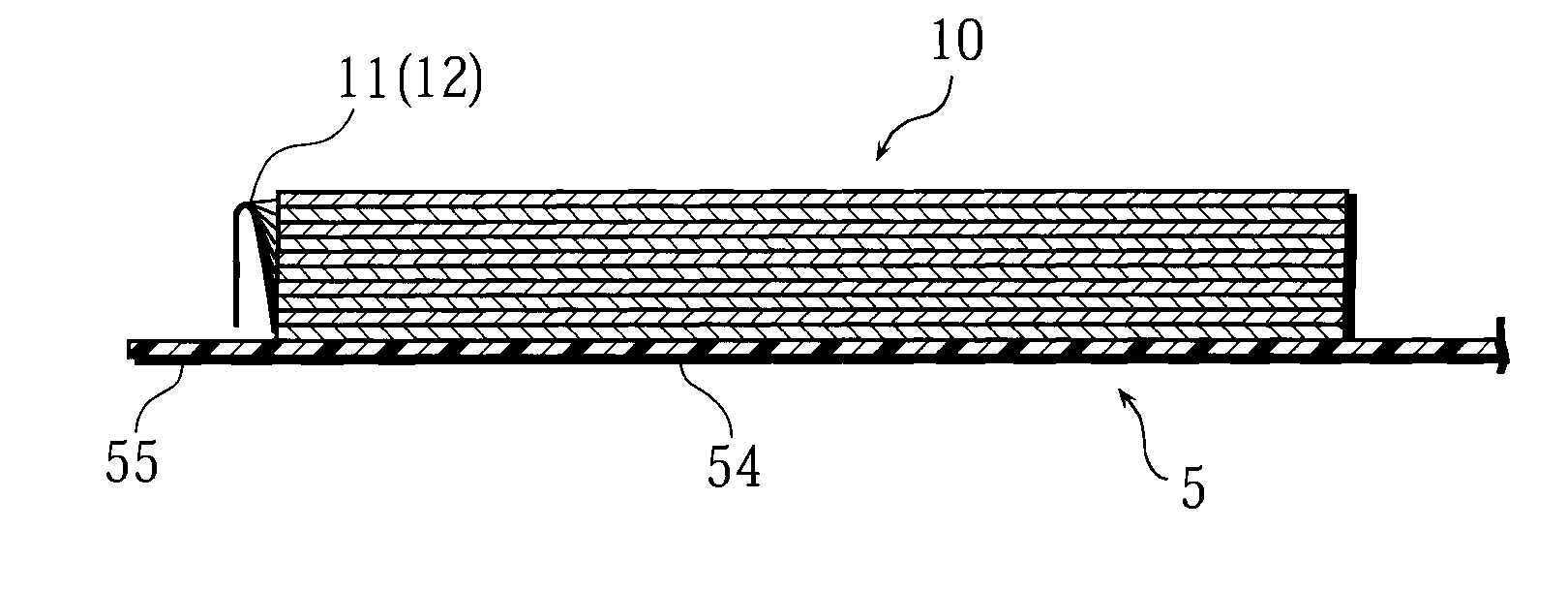
Stacked positive and negative electrode current collector tabs are bundled respectively in such a manner as to be gathered at one stacking direction-wise side (the upper end side) of the stacked electrode assembly. Portions of the bundled tabs extending from the bundled portion toward a tip side of the bundled tabs are bent toward the other stacking direction-wise side (lower end side) of the stacked electrode assembly, to form bent portions. The stacked electrode assembly is covered and fixed by an insulating sheet having insulation capability so as to cover both stacking direction-wise end faces thereof and surround the stacked electrode assembly in a tubular shape. A portion (slip-in piece) of the insulating sheet is inserted between the stacked electrode assembly and the bent portions of the positive and negative electrode current collector tabs. A portion (outer cover piece) of the insulating sheet covers the bent portions of the positive and negative electrode current collector tabs from outside.

Description

BACKGROUND OF THE INVENTION[0001]1. Field of the Invention[0002]The present invention relates to stack type batteries, and more particularly to high capacity stack type batteries used as power sources for, for example, robots, electric vehicles, and backup power sources.[0003]2. Description of Related Art[0004]In recent years, batteries have been used for not only the power source of mobile information terminal devices such as mobile-phones, notebook computers, and PDAs but also for such applications as robots, electric vehicles, and backup power sources. This has led to a demand for higher capacity batteries. Because of their high energy density and high capacity, lithium-ion batteries are widely used as the power sources for such applications as described above.[0005]The battery configurations of the lithium-ion batteries are broadly grouped into two types: one is a spirally-wound type lithium-ion battery, in which a spirally wound electrode assembly is enclosed in a battery case,...

Claims


Application Information

Patent Timeline
Patent Type & Authority Applications(United States)
IPC IPC(8): H01M10/02H01M50/119H01M50/121H01M50/129H01M50/136H01M50/533H01M50/54
CPCH01M2/0262H01M2/0275H01M10/0413H01M2/266H01M2/028Y02E60/10H01M50/54Y02P70/50H01M50/129H01M50/119H01M50/136H01M50/121H01M50/533
Inventor FUJIWARA, MASAYUKISHINYASHIKI, YOSHITAKAMAEDA, HITOSHIKUSUKAWA, MASAOTANI, YUJI
Owner SANYO ELECTRIC CO LTD
Learn More