
Variable gain control transformer and RF transmitter utilizing same

Active Publication Date: 2012-03-01
AVAGO TECH INT SALES PTE LTD
View PDF18 Cites 12 Cited by
  • Summary
  • Abstract
  • Description
  • Claims
  • Application Information

AI Technical Summary

Benefits of technology

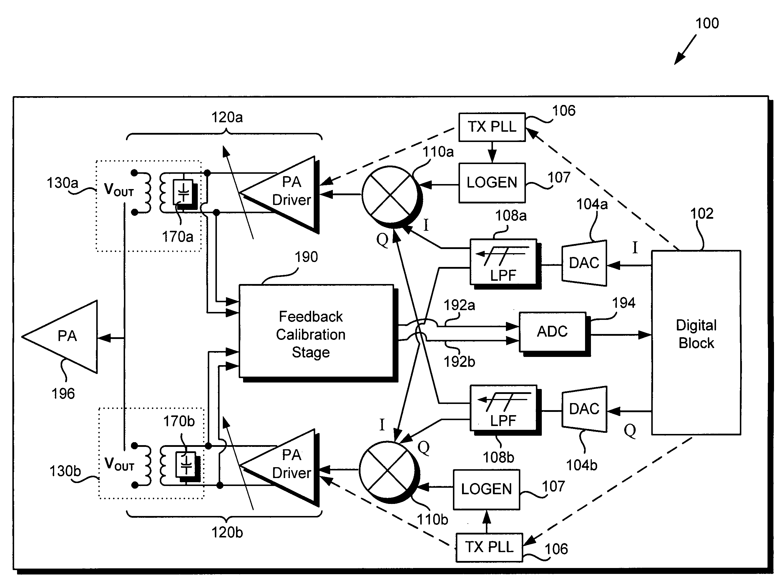
[0007]The present invention is directed to a variable gain control transformer and RF transmitter utilizing same, substantiall

Problems solved by technology

Unfortunately, this conventional approach to providing preamplification gain control is fraught with significant disadvantages, owing in part to the substantial inefficiencies resulting from the time and iterative testing required to coordinate calibration amongst the various lower frequency and higher frequency gain control stages.
Despite the disadvantages associated with conventional approaches, those approaches remain in widespread use due to the challenges posed by achieving adequate transmitter pre-amplification gain control at higher frequency using the PA driver stages alone.

Method used


Image

  • Variable gain control transformer and RF transmitter utilizing same
  • Variable gain control transformer and RF transmitter utilizing same
  • Variable gain control transformer and RF transmitter utilizing same

Examples


Embodiment Construction

[0014]The present invention is directed to a variable gain control transformer and RF transmitter utilizing same. Although the invention is described with respect to specific embodiments, the principles of the invention, as defined by the claims appended herein, can obviously be applied beyond the specifically described embodiments of the invention described herein. Moreover, in the description of the present invention, certain details have been omitted in order to not obscure the inventive aspects of the invention. The details left out are within the knowledge of a person of ordinary skill in the art.

[0015]The drawings in the present application and their accompanying detailed description are directed to merely exemplary embodiments of the invention. To maintain brevity, other embodiments of the invention, which use the principles of the present invention are not specifically described in the present application and are not specifically illustrated by the present drawings.

[0016]FIG...


PUM


Abstract

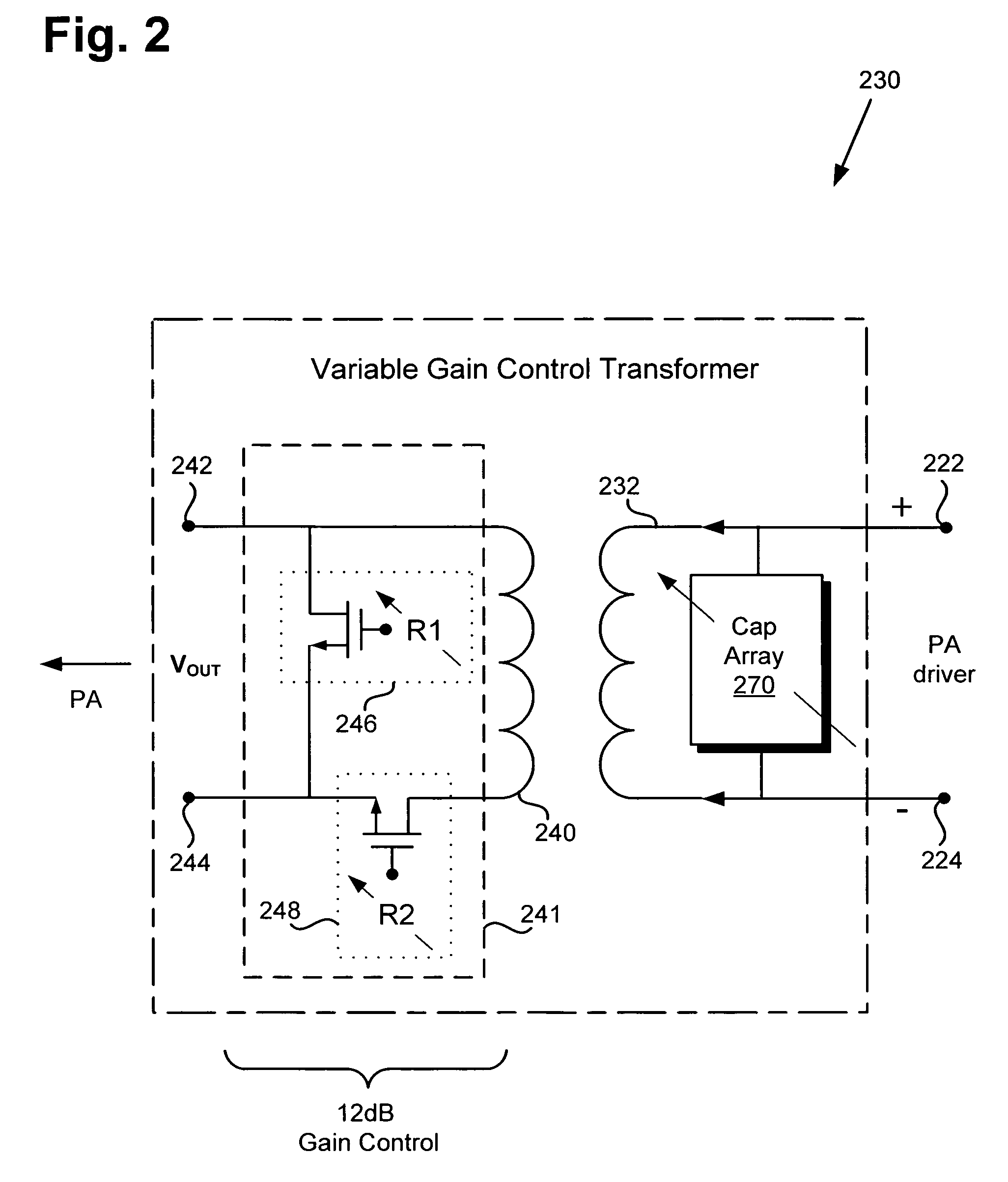
According to one embodiment, a variable gain control transformer comprises a primary winding connected to differential inputs of the variable gain control transformer, a secondary winding for providing a single ended output to a load, and an output control circuit coupled to the secondary winding, the output control circuit configured to provide up to approximately 12 dB of gain control. Variable gain control may be achieved using first and second variable resistors of the output control circuit, wherein the first and second variable resistors are implemented by respective first and second pluralities of source-drain resistances produced by respective corresponding first and second pluralities of selectable field-effect transistors (FETs). In one embodiment, the variable gain control transformer further comprises a variable capacitance tuning circuit coupled between the differential inputs, the variable capacitance tuning circuit implemented using a plurality of selectable fixed capacitance unit cells.

Description

BACKGROUND OF THE INVENTION[0001]1. Field of the Invention[0002]The present invention is generally in the field of electronic circuits and systems. More specifically, the present invention is in the field of communications circuits and systems.[0003]2. Background Art[0004]Transceivers are typically used in communications systems to support transmission and reception of communications signals through a common antenna, for example at radio frequency (RF) in a cellular telephone or other mobile communication device. A transmitter routinely implemented in such a transceiver in the conventional art may utilize several processing stages to condition and preamplify a transmit signal prior to passing the transmit signal to a power amplifier (PA). For example, the transmit signal may originate as a digital signal generated by a digital block of the transmitter. That digital signal is then typically converted into an analog baseband signal, by means of a digital-to-analog converter (DAC) for ...

Claims


Application Information

Patent Timeline
IPC IPC(8): H01Q11/12H01F27/42
CPCH03F3/245H01F27/42H03F2200/537H03F3/211
Inventor MIRZAEI, AHMADDARABI, HOOMAN
Owner AVAGO TECH INT SALES PTE LTD
Learn More