Urine Flow Monitoring Device and Method
- Summary
- Abstract
- Description
- Claims
- Application Information
AI Technical Summary
Benefits of technology
Problems solved by technology
Method used
Image
Examples
Embodiment Construction
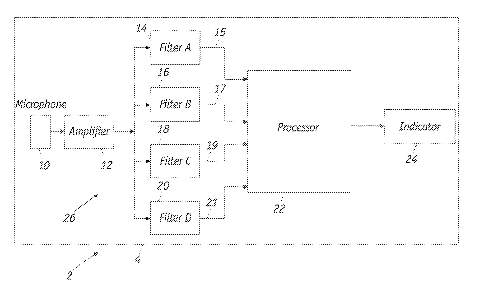
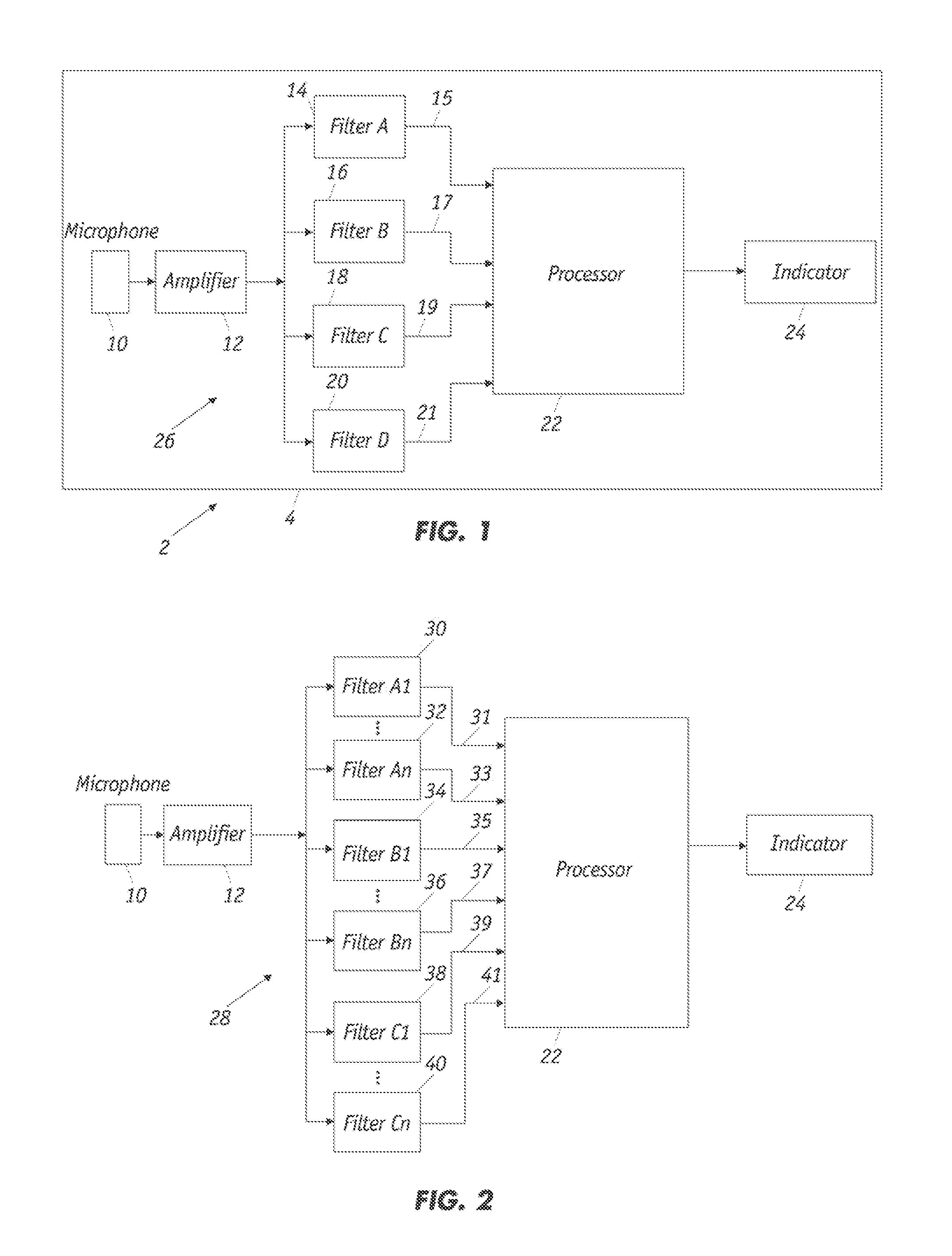
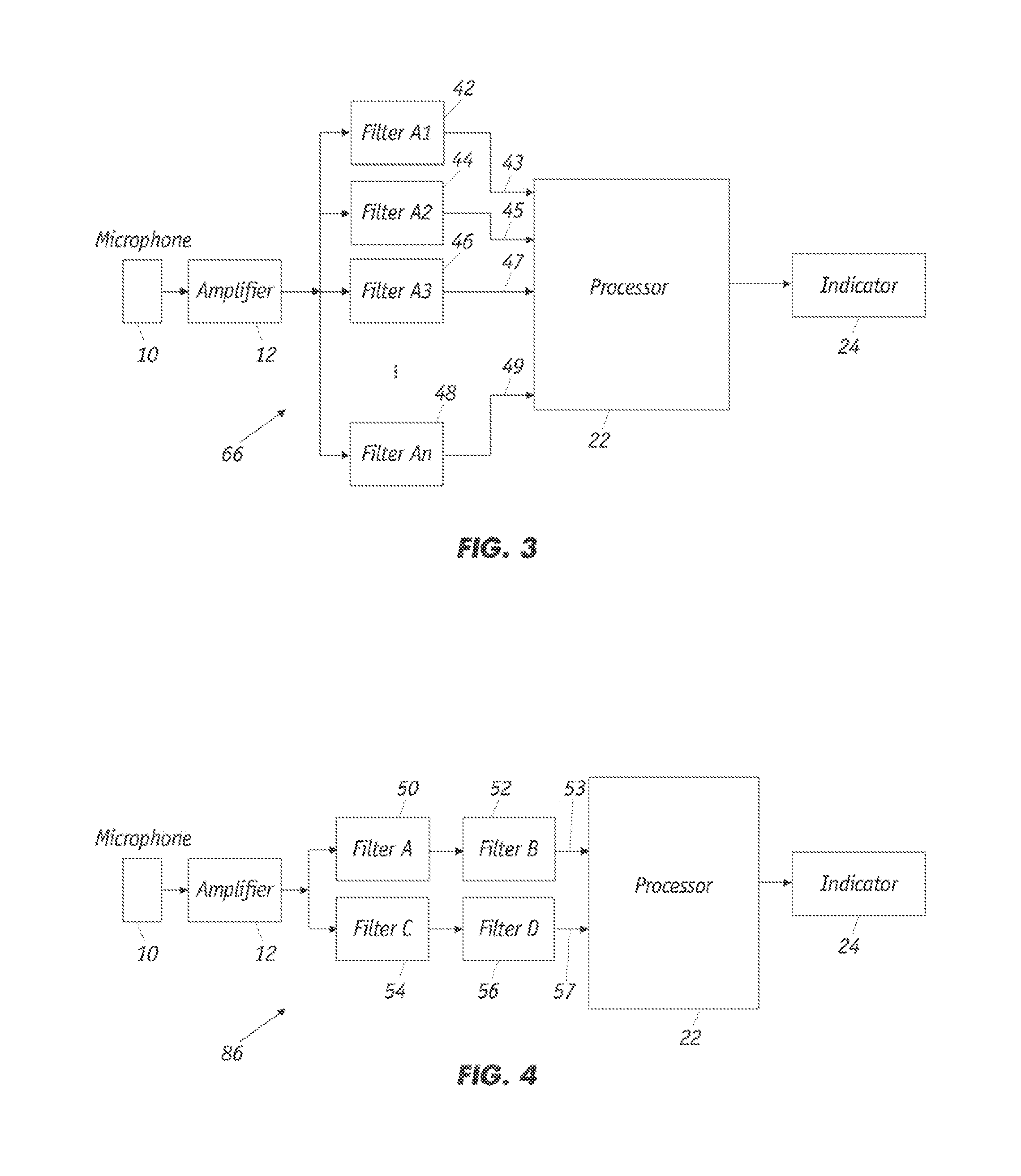
[0049]As shown in FIG. 1, the medical urine flow monitoring device 2 includes a housing 4 that encloses a microphone 10, amplifier 12, a bank of filters 26 that includes filters 14, 16, 18, and 20, a signal processor 22 and an output indicator 24. Electrical signals from microphone 10, which can be omnidirectional or unidirectional microphone(s), are amplified by amplifier 12 before being passed through a plurality of filters 14, 16, 18 and 20, that produce filtered signals 15, 17, 19, and 21, respectively. As further described herein, the bank of filters 26 serves to select the filtered signals of the desired frequency ranges to be analyzed by processor 22. The filters comprise one or more of a high-pass, low-pass, band-pass, and band-stop filter, for example, which are designated as Filters A, B, C and D, respectively. FIG. 1 depicts a four-channel urine flow-monitoring device with each channel employing a different type of filter. As further described herein, preferably one or mo...
PUM
 Abstract
Description
Claims
Application Information
 - R&D
- Intellectual Property
- Life Sciences
- Materials
- Tech Scout
- Unparalleled Data Quality
- Higher Quality Content
- 60% Fewer Hallucinations
Browse by: Latest US Patents, China's latest patents, Technical Efficacy Thesaurus, Application Domain, Technology Topic, Popular Technical Reports.
© 2025 PatSnap. All rights reserved.Legal|Privacy policy|Modern Slavery Act Transparency Statement|Sitemap|About US| Contact US: help@patsnap.com


