System and method for controlling one or more roller shades

a technology for controlling one or more roller shades and roller shades, which is applied in the direction of door/window protective devices, instruments, curtain suspension devices, etc., can solve the problems of limited accuracy of shade positioning, unsatisfactory aesthetics, and inability to guarantee the safety of all shades

Active Publication Date: 2012-03-01
CRESTRON ELECTRONICS
View PDF19 Cites 44 Cited by
  • Summary
  • Abstract
  • Description
  • Claims
  • Application Information

AI Technical Summary

Benefits of technology

[0035]In yet another embodiment, the optical sensor includes one of a high speed digital

Problems solved by technology

A common problem with typical motorized roller shades is that when the shade is raised or lowered, the motorized drive system, which moves the shade at a constant velocity, abruptly starts rotating the shade, winds or unwinds the shade at the constant velocity, and then abruptly stops rotating the shade when the shade reaches a selected position.
Consequently, during raising or lowering of the shade, the shade moves with an aesthetically unpleasing “jerky” motion.
Further, sometimes the shade undershoots the selected position because the shade is abruptly stopped too early.
This indirect method

Method used


Image

  • System and method for controlling one or more roller shades
  • System and method for controlling one or more roller shades
  • System and method for controlling one or more roller shades

Examples


Embodiment Construction

[0246]Reference will now be made to the exemplary embodiments illustrated in the drawings, and specific language will be used herein to describe the same. It will nevertheless be understood that no limitation of the scope of the invention is thereby intended. Alterations and further modifications of the inventive features illustrated herein, and additional applications of the principles of the inventions as illustrated herein, which would occur to one skilled in the relevant art and having possession of this disclosure, are to be considered within the scope of the invention.

[0247]Unless the context clearly requires otherwise, throughout the description and the claims, the words ‘comprise’, ‘comprising’, and the like are to be construed in an inclusive sense as opposed to an exclusive or exhaustive sense; that is to say, in the sense of “including, but not limited to”.

MODE(S) FOR CARRYING OUT THE INVENTION

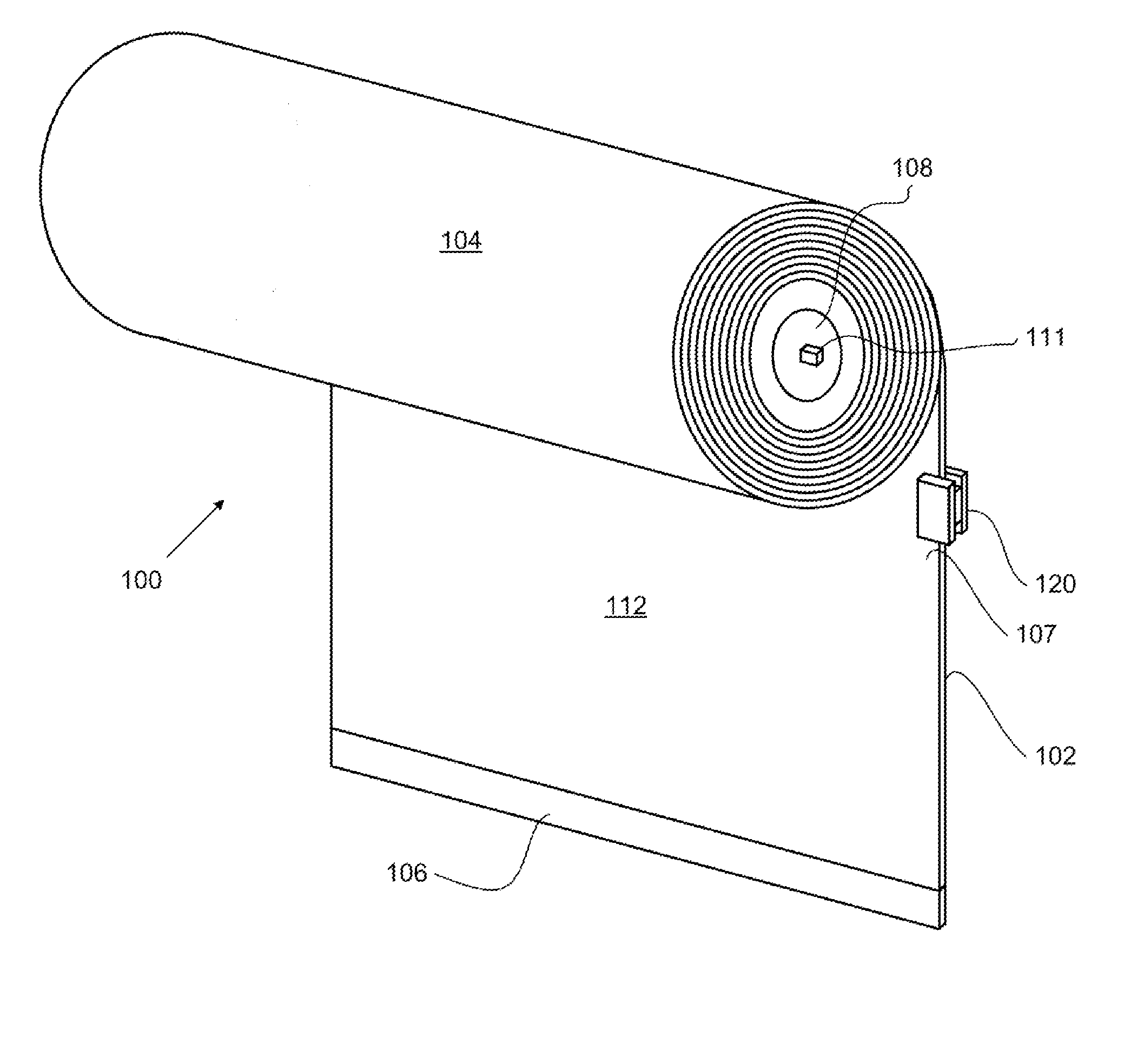
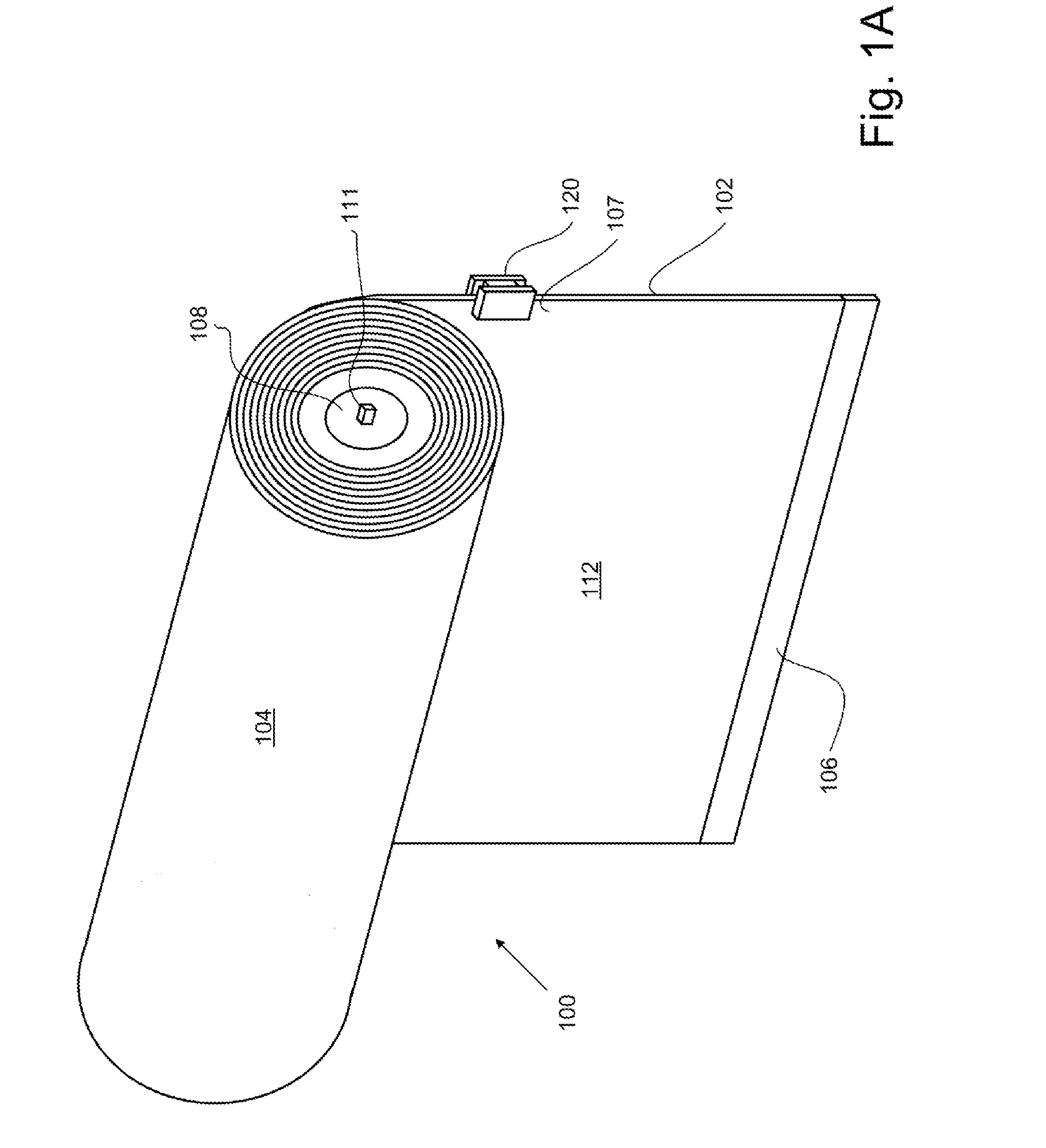
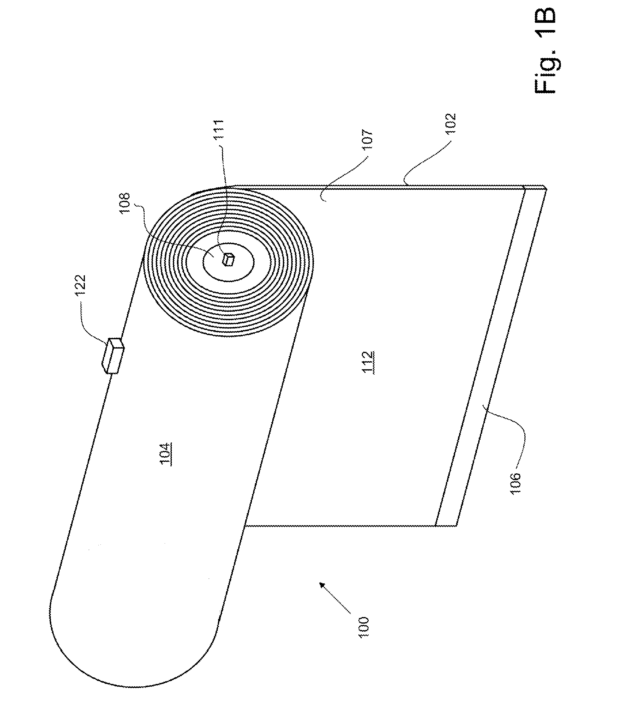
[0248]The present invention involves a system and a method for smoothly (i.e., ...


PUM


Abstract

Presented is a roller shade system that includes a flexible shade material having a lower end, a rotatably supported roller tube that windingly receives the shade material, a stepper motor that operably engages the roller tube to rotate the roller tube to move the lower end of the shade material between a first position and a second position, an optical sensor configured for capturing an image frame of the shade material at linear positions along the shade material as the lower end of the flexible shade material moves from the first position to the second position, and a stepper motor controller configured for controlling the frequency of input pulses to the stepper motor to move the lower end of the flexible shade material from the first position to the second position at a substantially constant linear velocity in response to position information obtained from the plurality of captured image frames.

Description

BACKGROUND OF THE INVENTION[0001]1. Technical Field[0002]The present invention generally relates to raising and lowering roller shades, and more particularly to raising and lowering a roller shade to a selected position at a substantially constant linear velocity, and raising and lowering a plurality of roller shades synchronously.[0003]2. Background Art[0004]A typical motorized roller shade includes a flexible shade fabric wound onto an elongated roller tube. The roller tube is rotatably supported so that a lower end of the flexible shade fabric can be raised (i.e., wound) or lowered (i.e., unwound) by rotating the roller tube. The roller tube is rotated by a motorized drive system.[0005]A common problem with typical motorized roller shades is that when the shade is raised or lowered, the motorized drive system, which moves the shade at a constant velocity, abruptly starts rotating the shade, winds or unwinds the shade at the constant velocity, and then abruptly stops rotating the ...

Claims


Application Information

Patent Timeline
IPC IPC(8): E06B9/68G05D3/12H04N7/18G06K9/00E06B9/42E06B9/44
CPCE06B9/42E06B9/70Y02B80/50E06B2009/6818E06B2009/6872E06B9/72Y02A30/24Y02B80/00
Inventor FELDSTEIN, GEORGELABOSCO, MARKKUMAR, RUSSIKESH
Owner CRESTRON ELECTRONICS
Why Eureka
Try Eureka