Systems and methods for monitoring and diagnostics of photovoltaic solar modules in photovoltaic systems

a photovoltaic solar module and photovoltaic system technology, applied in the field of monitoring and diagnostics, can solve the problems of low power consumption, degraded performance of photovoltaic modules, and often degraded performance of photovoltaic (pv) modules (e.g., solar panels), and achieve the effect of low cost and low power consumption

Inactive Publication Date: 2012-03-08
ALION
View PDF8 Cites 30 Cited by
  • Summary
  • Abstract
  • Description
  • Claims
  • Application Information

AI Technical Summary

Benefits of technology

[0014]Many benefits are achieved by way of the present invention over conventional techniques. Certain embodiments of the present invention provide a system and method to monitor performance of individual photovoltaic modules at low cost and / or with low power consumption. For example, the system and method is applied to photovoltaic installations with a large number of photovoltaic modules.

Problems solved by technology

Performance of photovoltaic (PV) modules (e.g., solar panels) often degrades over time.
If the performance of a photovoltaic module degrades significantly, other modules that are connected in series with the degraded module (e.g., in a string of solar panels) might end up not operating at the optimal power point (e.g., the Pmax point on the current-voltage curve).
Additionally, the performance of photovoltaic modules can degrade if their surface areas are covered by accumulated dirt.
It is also possible that one or more photovoltaic modules display catastrophic failures.
For example, a single degraded, or completely faulty, photovoltaic module can have an adverse effect on the power production of other well-functioning modules (e.g., other solar panels in the string).
But after the modules are installed in the field (e.g., as parts of a photovoltaic array), it can be cumbersome to disconnect the modules and perform such a test on individual modules.
Furthermore, disconnecting one or more modules from a PV string under high voltage conditions may be dangerous and can also interrupt the power production.
So far, the conventional technologies for monitoring individual PV modules often are expensive and power consuming.
The problem with this approach is that the cost of such a wireless unit is considerable and the power consumed by the wireless unit is also significant.
Additionally, the amount of information that needs to be conveyed is low, so the use of high-bandwidth wireless technology may be an overkill solution for the problems at hand.
Hence this conventional technology is very expensive both from a monetary as well as power consumption point of view.
However, the drawback with this method is that once it is discovered that there is an issue with a particular string, there is usually no way of knowing which, or which ones, of the PV modules in that string have a problem.

Method used


Image

  • Systems and methods for monitoring and diagnostics of photovoltaic solar modules in photovoltaic systems
  • Systems and methods for monitoring and diagnostics of photovoltaic solar modules in photovoltaic systems
  • Systems and methods for monitoring and diagnostics of photovoltaic solar modules in photovoltaic systems

Examples


Embodiment Construction

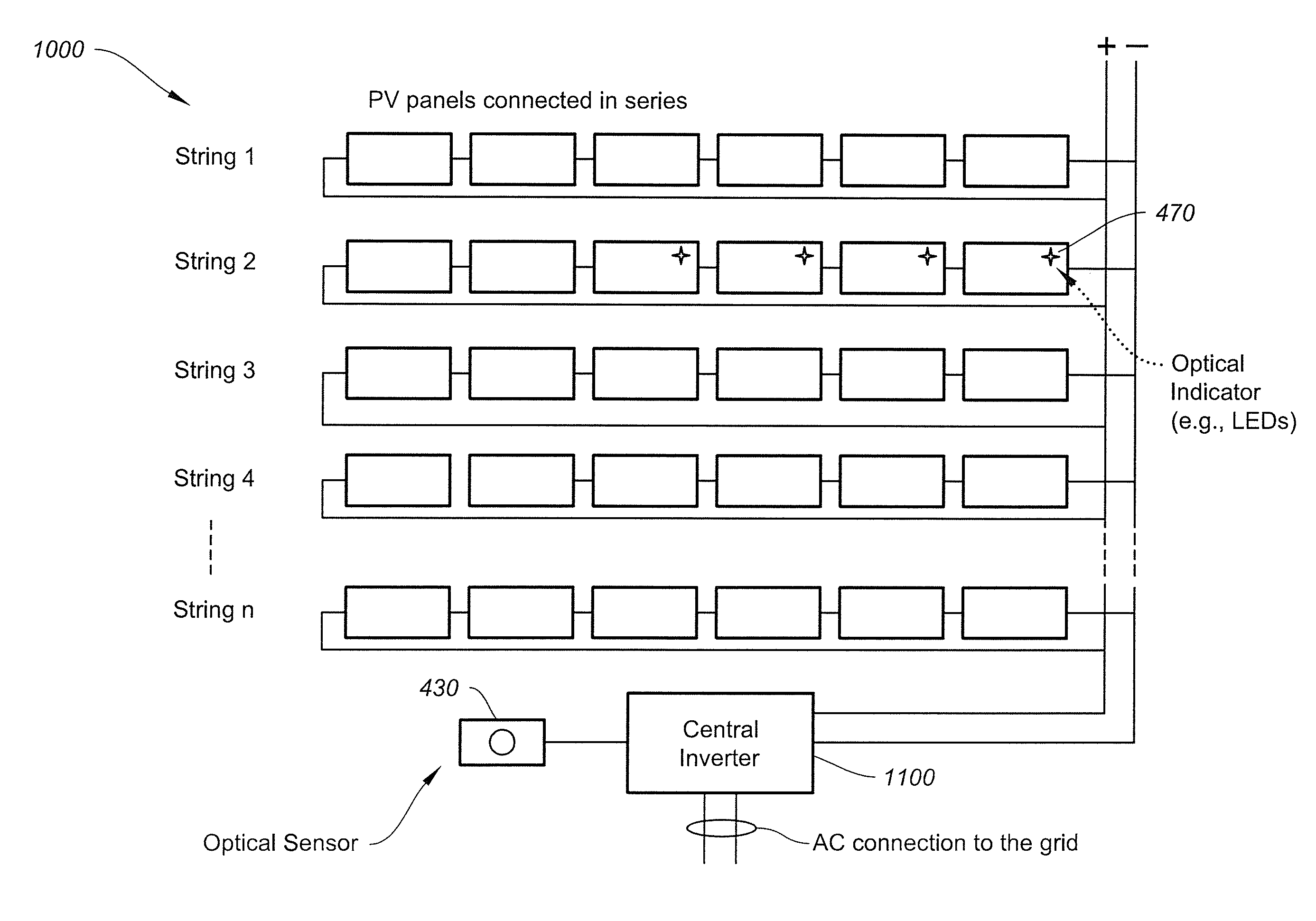
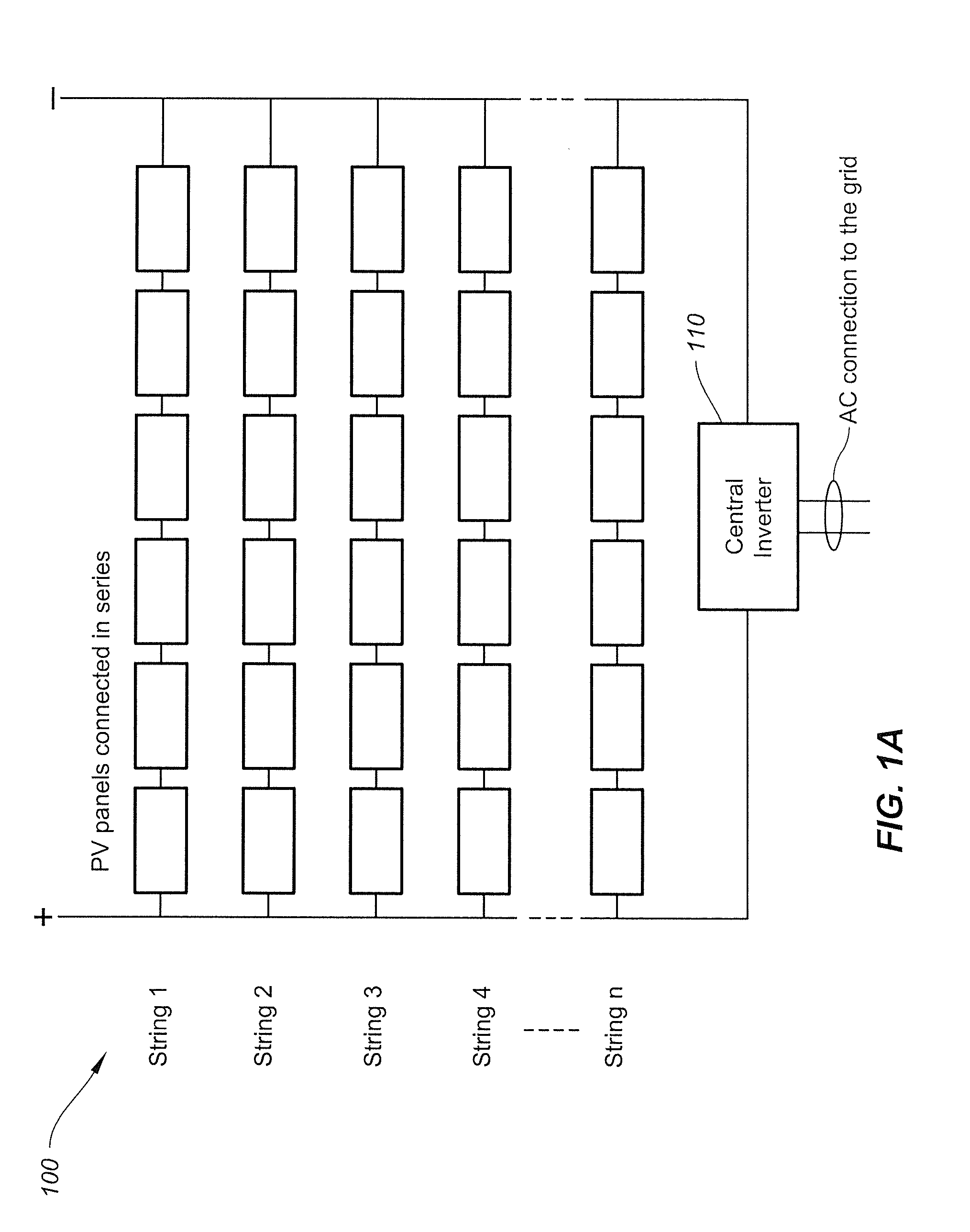
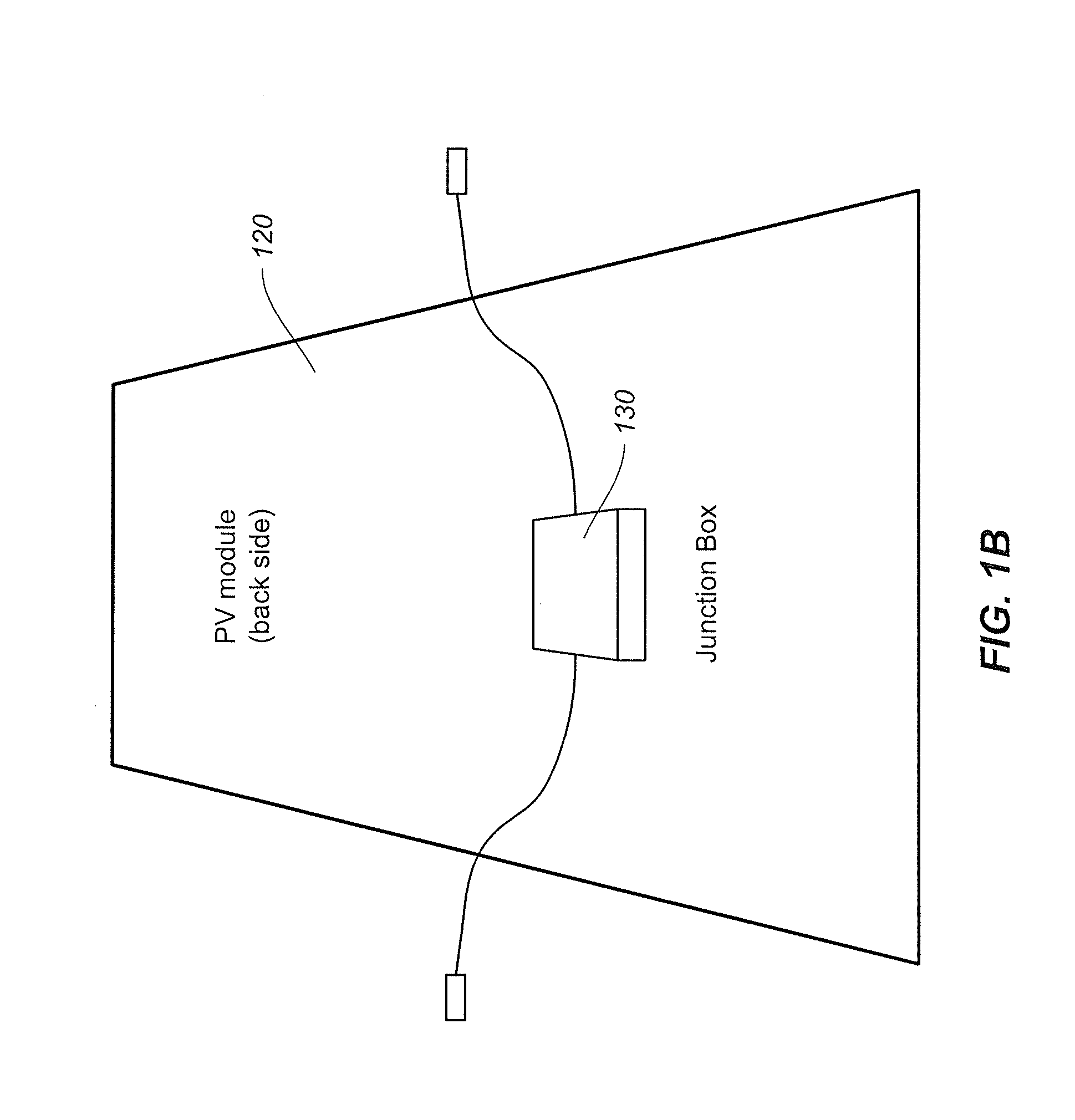
[0026]The present invention is directed to monitoring and diagnostics. More particularly, the invention provides systems and methods for monitoring and diagnostics of photovoltaic modules. Merely by way of example, the invention has been applied to photovoltaic systems. But it would be recognized that the invention has a much broader range of applicability.

[0027]FIG. 3 is a simplified diagram showing a method for monitoring a photovoltaic module according to one embodiment of the present invention. This diagram is merely an example, which should not unduly limit the scope of the claims. One of ordinary skill in the art would recognize many variations, alternatives, and modifications. The method 300 for monitoring a photovoltaic module includes a process 310 for initiating monitoring, a process 320 for measuring one or more module parameters, a process 330 for collecting one or more measurement results of one or more measured parameters, a process 340 for transmitting one or more col...


PUM


Abstract

A method and system for monitoring a photovoltaic module. The method includes initiating a monitoring process for a photovoltaic module at a predetermined time. The photovoltaic module is connected to at least another module in a photovoltaic string as a part of a photovoltaic array. Additionally, the method includes measuring one or more parameters of the photovoltaic module by a monitoring circuit. The one or more parameters include a module current flowing through the photovoltaic module, a module voltage across the photovoltaic module, and a module temperature of the photovoltaic module. Also, the method includes collecting one or more measurement results of the one or more parameters, transmitting the one or more collected results using one or more radio-frequency signals, and processing information associated with the one or more transmitted results.

Description

1. CROSS-REFERENCES TO RELATED APPLICATIONS[0001]This application claims priority to U.S. Provisional No. 61 / 312,523, filed Mar. 10, 2010, commonly assigned and incorporated by reference herein for all purposes.2. BACKGROUND OF THE INVENTION[0002]The present invention is directed to monitoring and diagnostics. More particularly, the invention provides systems and methods for monitoring and diagnostics of photovoltaic modules. Merely by way of example, the invention has been applied to photovoltaic systems. But it would be recognized that the invention has a much broader range of applicability.[0003]Photovoltaics convert sunlight into electricity, providing a desirable source of clean energy. FIG. 1A is a simplified diagram of a conventional photovoltaic array. The photovoltaic array 100 includes strings 1, 2, 3, 4, . . . n, where n is a positive integer larger than or equal to 1. Each string includes photovoltaic (PV) modules (e.g., solar panels) that are connected in series. The ph...

Claims


Application Information

Patent Timeline
Patent Type & Authority Applications(United States)
IPC IPC(8): G01R31/26
CPCH02S50/10Y02E10/50
Inventor SWAHN, ANDERS
Owner ALION
Why Eureka
Try Eureka