
Imaging system and pixel signal readout method

a technology of image signal and readout method, which is applied in the field of imaging system, can solve the problems of disadvantage of conventional contrast detection autofocus technology, achieve high visibility, accelerate contrast detection autofocus operation, and reduce frame rate

Inactive Publication Date: 2012-03-08
RICOH IMAGING COMPANY
View PDF4 Cites 26 Cited by
  • Summary
  • Abstract
  • Description
  • Claims
  • Application Information

AI Technical Summary

Benefits of technology

[0006]Accordingly, one aspect of the present invention is to accelerate the contrast-detect autofocus operation while enabling an indication of a focus-verification image with high visibility.
[0007]According to an aspect of the present invention, an imaging system is provided that includes a frame rate setter and an exposure evaluator. The frame rate setter sets a frame rate used in a focusing operation. The frame rate is set faster than a normal frame rate. The exposure evaluator evaluates an exposure of a focusing image based on pixel signals from a focusing image area that are read out at the frame rate. The frame rate is reduced when the exposure is evaluated as an underexposure, and the focusing operation is then carried out at a reduced frame rate.
[0008]According to another aspect of the present invention, a pixel signal readout method is provided that includes setting a frame rate used in a focusing operation and evaluating an exposure of a focusing image based on pixel signals from a focusing image area that are readout at said frame rate. The frame rate, which is set faster than a normal frame rate, is reduced when the exposure is evaluated as an underexposure so that the pixel signals are read out at a reduced frame rate.

Problems solved by technology

Although a high-speed autofocus operation is preferable, the conventional contrast-detect autofocus technology is at a disadvantage when carrying out high-speed focusing because it must read out all signals within an actual pixel area (an area within an effective pixel area in which the quality of an image is guaranteed).

Method used


Image

  • Imaging system and pixel signal readout method
  • Imaging system and pixel signal readout method
  • Imaging system and pixel signal readout method

Examples


Embodiment Construction

[0019]The present invention is described below with reference to the embodiments shown in the drawings.

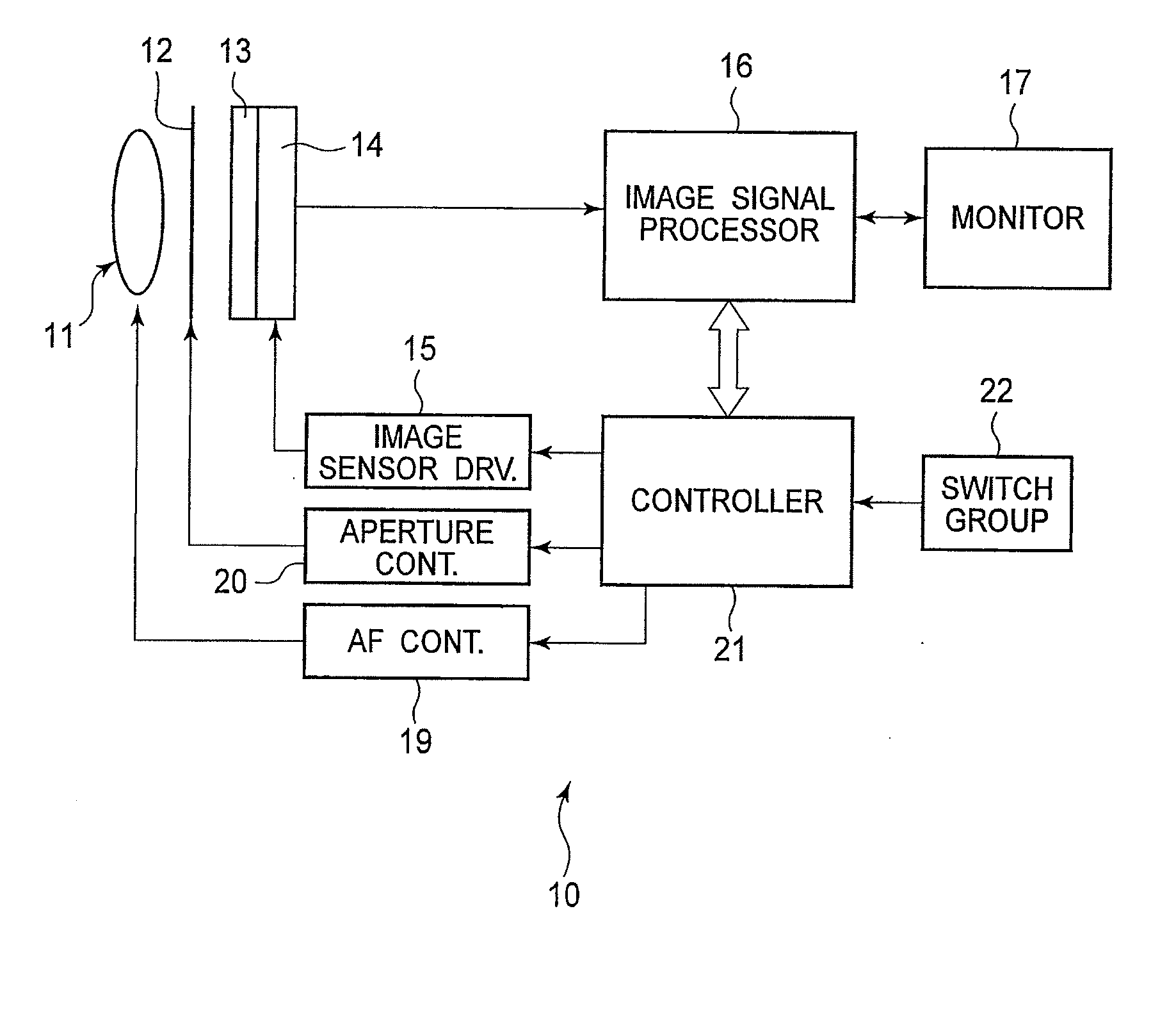
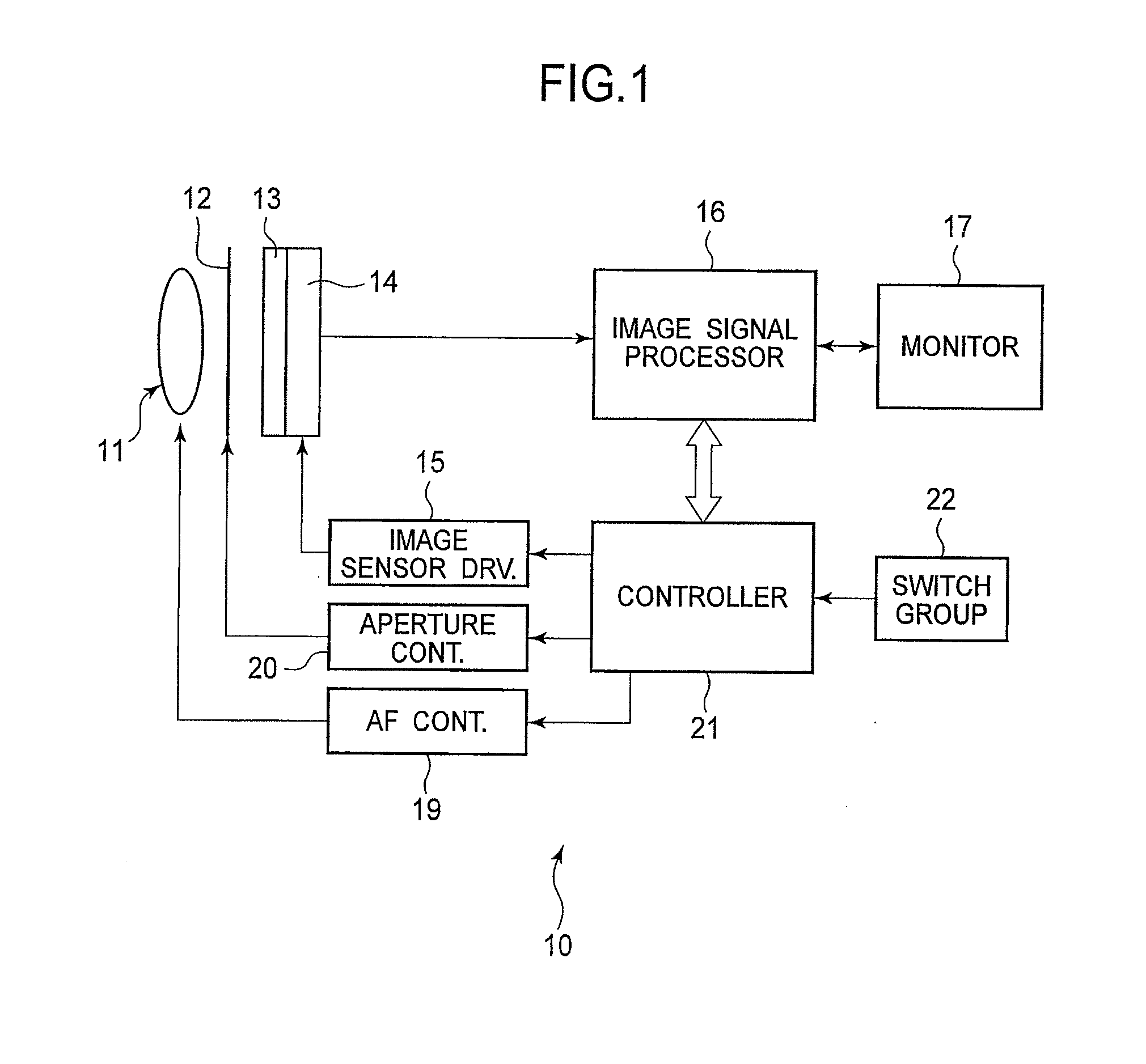
[0020]FIG. 1 is a block diagram schematically illustrating the general structure of a digital camera to which an embodiment of the present invention is applied.

[0021]The digital camera 10 may be a digital single-lens reflex camera. Light made incident to a lens system 11 forms an image on an imaging surface of a CMOS image sensor 14, for example, through an aperture 12 and a color filter array 13. The CMOS image sensor 14 may be controlled by drive signals from an image sensor driver 15. Image signals obtained by the CMOS image sensor 14 may be fed to an image signal processor 16 to be subjected to various types of image signal processing that are well known in the art, and in turn, the image may be displayed on a monitor 17.

[0022]An AF controller 19 may control the positions of the lenses in the lens system 11 to carry out the autofocus operation. Further, an aperture controller 2...


PUM


Abstract

An imaging system including a frame rate setter and an exposure evaluator. The frame rate setter sets a frame rate used in a focusing operation. The frame rate is set faster than a normal frame rate. The exposure evaluator evaluates the exposure of a focusing image based on pixel signals read out from a focusing image area at the frame rate. The frame rate is reduced when the exposure is evaluated as an underexposure and the focusing operation is carried out at a reduced frame rate.

Description

BACKGROUND OF THE INVENTION[0001]1. Field of the Invention[0002]The present invention relates to a device for reading out image signals from a CMOS image sensor and a method thereof.[0003]2. Description of the Related Art[0004]A contrast-detect autofocus (AF) function has been employed by various types of digital cameras where, in general, a focusing image is temporarily displayed on a monitor of the camera for a photographer to check whether or not the image is adequately in focus. However, the size of the monitor provided on the camera is usually not sufficient for a photographer to verify the quality or conditions of the focusing image when the entire image is represented on the display. In order to overcome such problems, a camera disclosed in KOKAI 2004-242010 enlarges an area with the highest degree of focusing and further indicates a subarea within the enlarged image having the highest focusing degree by framing the subarea.SUMMARY OF THE INVENTION[0005]Although a high-speed ...

Claims


Application Information

Patent Timeline
Patent Type & Authority Applications(United States)
IPC IPC(8): H04N5/235
CPCH04N5/2357H04N5/23212H04N23/745
Inventor TANAKA, HIROYUKI
Owner RICOH IMAGING COMPANY
Learn More