
Eureka
For R&D, Eureka makes reading and utilizing patents & technical documents easy.
Eureka AIR
Designed for self-driven R&D workflows. Generate viable solutions, solve complex R&D challenges, empower your innovation with AI.

Eureka Materials
Designed for material experts only. Revolutionize your material R&D, from search, analyze, to developing new materials.

TechResearch
Generate reliable direction feasibility study reports for your R&D in just a few steps.

TechSeek
Discover and master advanced knowledge NOW. Basics, ideas, possibilities, all at once.

TechMind
As an expert in R&D Theories, TechMind can generates customized viable solutions instantly.

TechRisk
Analyze your overall solution with one click, know your potential R&D risks in advance.

TechMonitor
Get weekly tech updates, stay abreast of the latest tech innovations and key insights.
Apparatus for determining thickness of a banknote
- Summary
- Abstract
- Description
- Claims
- Application Information
AI Technical Summary
Benefits of technology
Problems solved by technology
Method used
Image

Examples
Example
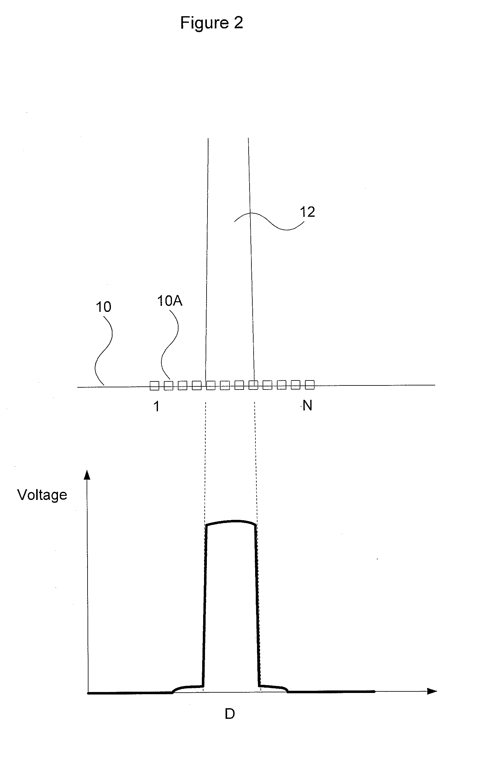
[0037]In a first embodiment, the sensor array 10 is constructed by forming an array of photo-sensing elements 10A on a same piece of silicon substrate in high density, for example 200 to 1000 DPI pixel resolution and been packaged in a single IC format. This kind of formation can be found in sensor units like 2-D CCD or CMOS chips used in cameras or 1-D CCD or CIS units used in linear scanners. The active area formed by this method is roughly same size as the exposed silicon area on the IC for light detection.
Example
[0038]In a second embodiment, the sensor array 10 is constructed by soldering discrete photo-sensors 10A onto a PCB or mounting them in a mechanical holder to form a bed of a closely populated photo-sensor assembly. The discrete photo-sensors 10A may be surface mounted photo-transistors or photo-diodes. This assembly, however gives a much lower pixel resolution (less than 20 DPI) as the die size of each discrete photo-sensor is much bigger than that of the first embodiment and its enclosure material makes it too bulky to fit a lot of them in a small area. Often there are gaps between each photo-sensor 10A and inaccuracy is introduced.
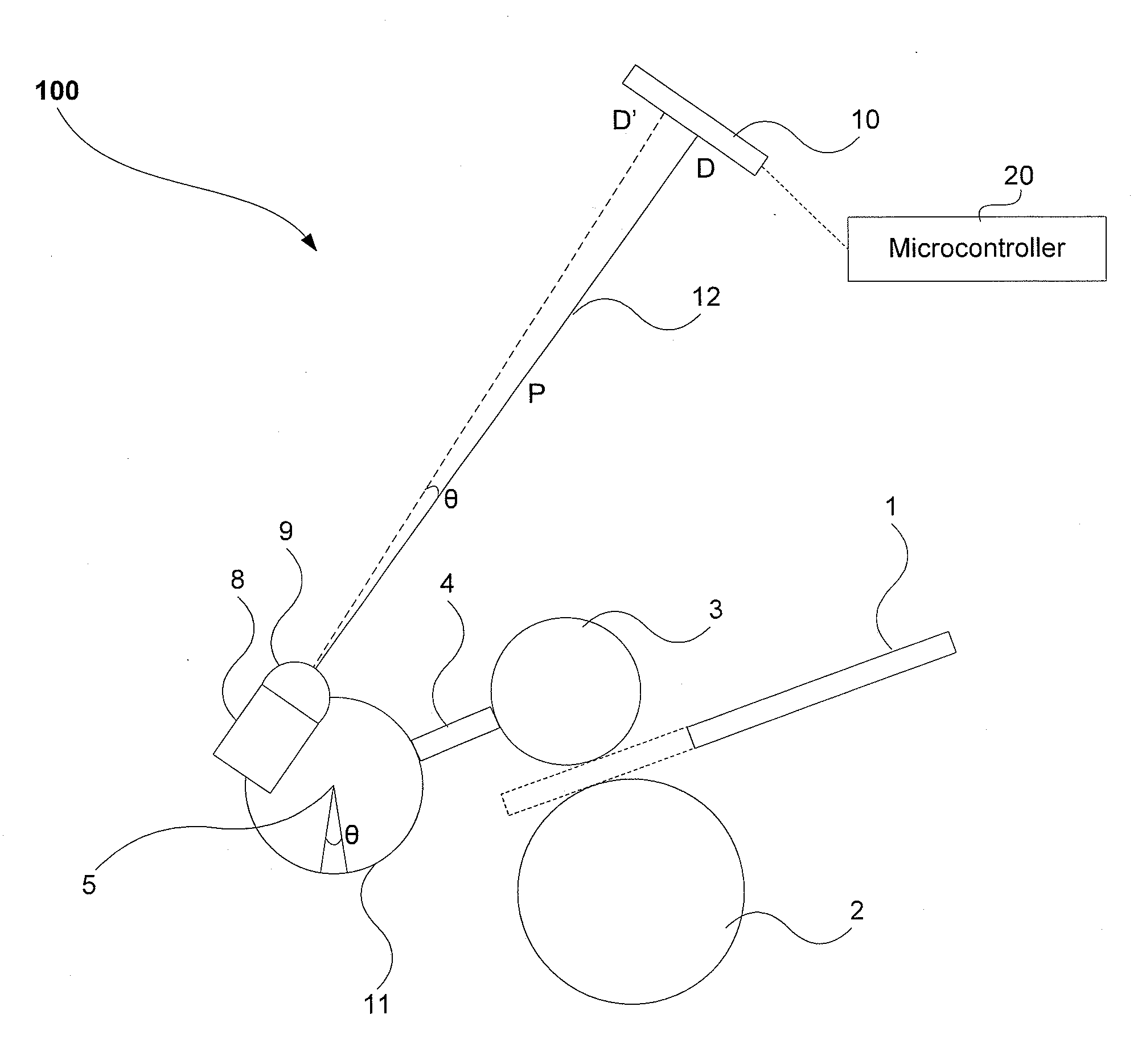
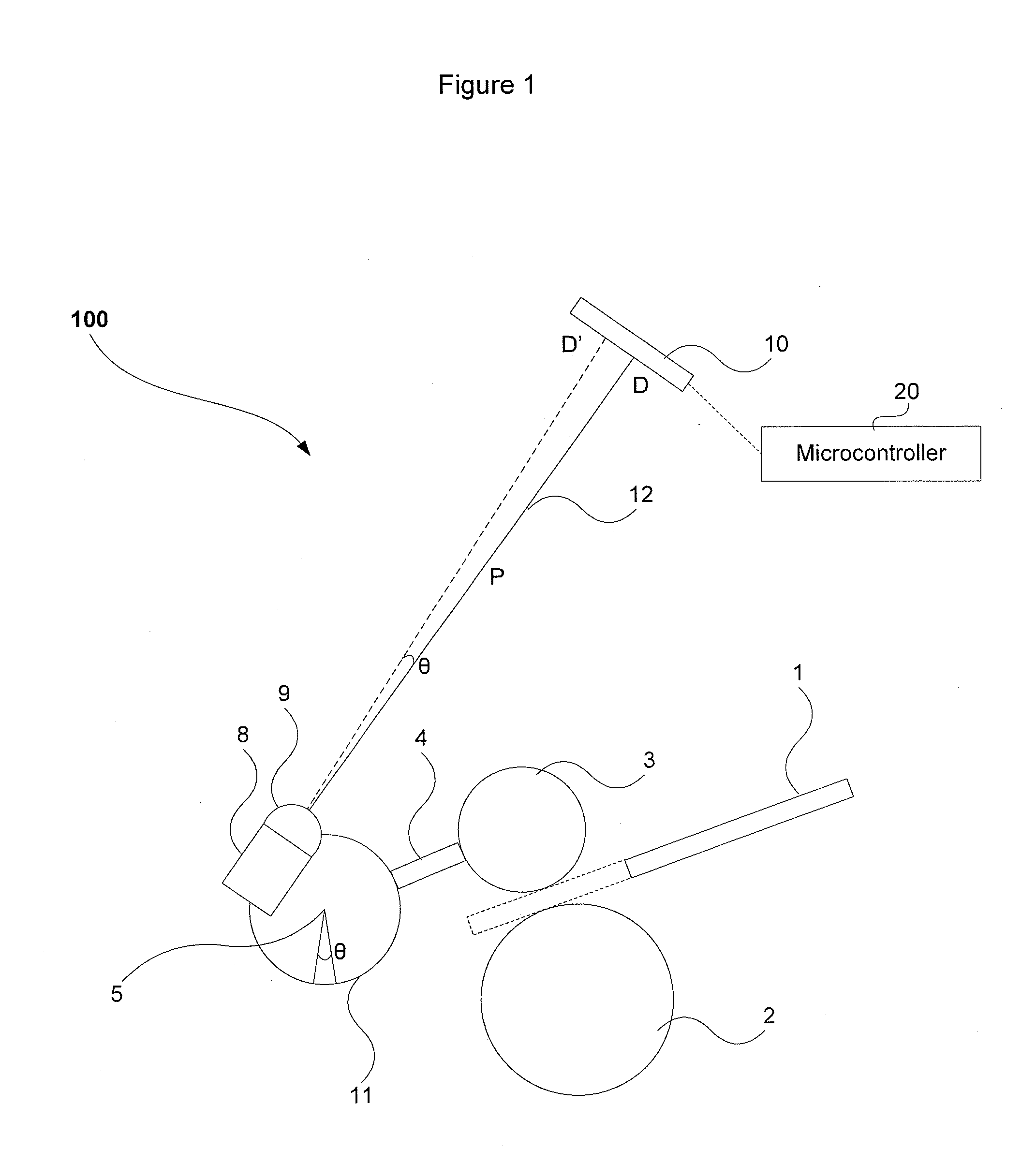
[0039]The light generator 8 generates an optical beam 12 from a light source such as a laser diode, a visible light source or an invisible infrared emitter. The light generator 8 is operated under a constant power source or a pulsed On-Off control circuit to converse energy and life of the light generator 8. An aperture control 9, for example a converge...
PUM
 Abstract
Description
Claims
Application Information
 - R&D Engineer
- R&D Manager
- IP Professional
- Industry Leading Data Capabilities
- Powerful AI technology
- Patent DNA Extraction
Browse by: Latest US Patents, China's latest patents, Technical Efficacy Thesaurus, Application Domain, Technology Topic, Popular Technical Reports.
© 2024 PatSnap. All rights reserved.Legal|Privacy policy|Modern Slavery Act Transparency Statement|Sitemap|About US| Contact US: help@patsnap.com