
Method for amplifying a burst optical signal, burst optical amplifier and system, and communications system

a technology of optical amplifier and amplifier, applied in the field of communication technologies, can solve the problems of signal distortion, problem of discontinuous burst optical signals, and time-consuming, and achieve the effect of avoiding signal distortion

Inactive Publication Date: 2012-03-08
HUAWEI TECH CO LTD
View PDF4 Cites 9 Cited by
  • Summary
  • Abstract
  • Description
  • Claims
  • Application Information

AI Technical Summary

Benefits of technology

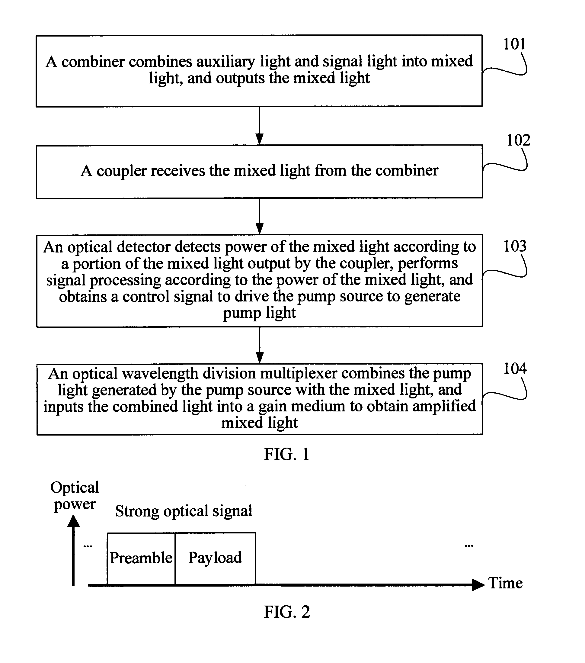
[0008]Embodiments of the present invention provide a method for amplifying a burst optical signal, a burst optical amplifier and system, and a communications system, which prevent a surge phenomenon so as to avoid signal distortion.
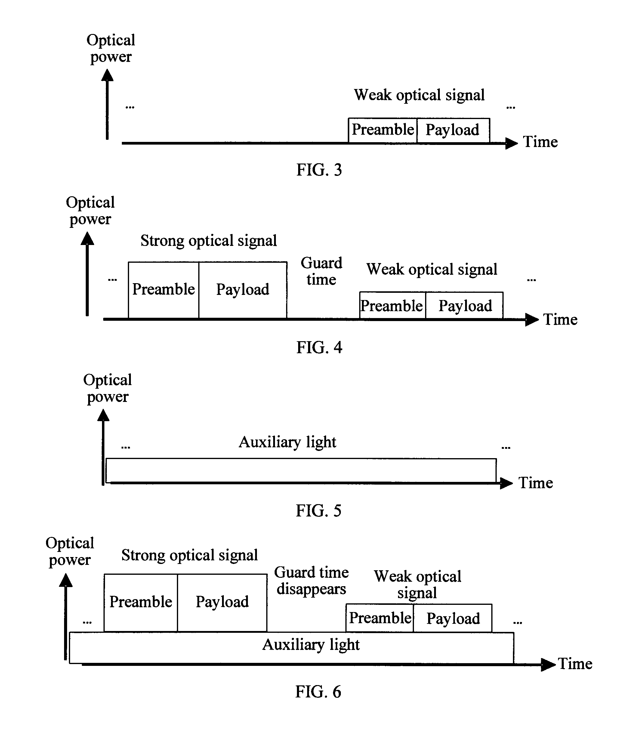
[0029]In the above method for amplifying a burst optical signal, the burst optical amplifier, and the communications system, because the auxiliary light or non-burst light may always exist, the burst optical amplifier or the optical amplifier may always operate in a state of amplifying light. The pump light exists in a gain medium, and the pump light may directly amplify the entered signal light, thereby reducing the delay time when the burst optical amplifier or the optical amplifier is enabled, improving the transient response speed of the burst optical amplifier or the optical amplifier, and reducing or preventing a surge phenomenon, so as to prevent signal distortion. Power of the auxiliary light does not change with power of the signal light. Therefore, a hole-burning phenomenon is prevented.

Problems solved by technology

As a result, burst optical signals are discontinuous not only in terms of time but also in terms of the power amplitude.
If an ordinary optical amplifier, for example, an optical amplifier based on the Automatic Gain Control (AGC), Automatic Current Control (ACC), Automatic Power Control (APC), and optical compensation technology, is currently used, because the response time constant of a typical transient effect of the ordinary optical amplifier is on a nanosecond scale, surge may occur after a burst optical signal is amplified by the ordinary optical amplifier, which results in signal distortion.
In addition, in other non-PON optical transmission technologies, when it is necessary to amplify burst light, the same problem may occur.

Method used


Image

  • Method for amplifying a burst optical signal, burst optical amplifier and system, and communications system
  • Method for amplifying a burst optical signal, burst optical amplifier and system, and communications system
  • Method for amplifying a burst optical signal, burst optical amplifier and system, and communications system

Examples


Embodiment Construction

[0039]The technical solutions of the present invention are hereinafter described in detail through embodiments and the accompanying drawings.

[0040]In the prior art, the response time constant of the typical transient effect of an ordinary doped optical amplifier is relatively large. When the ordinary optical amplifier amplifies burst light, a surge phenomenon may occur or the speed of enabling the optical amplifier may be too slow, resulting in transmission signal distortion. An embodiment of the present invention provides a method, where auxiliary light is added into an optical signal input to an optical amplifier, so that non-burst light may always pass through the optical amplifier, thereby preventing the surge phenomenon and avoiding a phenomenon that the speed of enabling the optical amplifier is too slow. Because power of the auxiliary light is set to be independent from power of signal light, the power of the auxiliary light may be set very low, so as to avoid the influence o...


PUM


Abstract

A method for amplifying a burst optical signal, a burst optical amplifier and system, and a communications system are provided according to embodiments of the present invention. The method includes: combining an auxiliary light and a signal light into a mixed light and outputting the mixed light, where the auxiliary light is a non-burst light, the signal light is a burst light, and power of the auxiliary light is set to be independent from power of the signal light; generating a pump light; and combining the pump light with the mixed light and inputting the combined light into a gain medium, so as to obtain an amplified mixed light. Present invention has the following advantages: reducing the delay time of enabling the burst optical amplifier, improving the transient response speed of the burst optical amplifier, and preventing the generation of a surge phenomenon, so as to prevent the generation of signal distortion.

Description

CROSS-REFERENCE TO RELATED APPLICATIONS[0001]This application is a continuation of International Application No. PCT / CN2010 / 072862, filed on May 18, 2010, which claims priority to Chinese Patent Application No. 200910085507.0, filed on May 22, 2009 and Chinese Patent Application No. 200910151155.4, filed on Jul. 27, 2009, all of which are hereby incorporated by reference in their entireties.FIELD OF THE INVENTION[0002]The present invention relates to the field of communications technologies, and in particular, to a method for amplifying a burst optical signal, a burst optical amplifier and system, and a communications system.BACKGROUND OF THE INVENTION[0003]With the rapid development of communications technologies, the Passive Optical Network (PON) technology is one of the most widely used Fiber To The Home (FTTH) technologies in access networks. PONs of different types have basically the same network architecture, which includes an Optical Line Terminal (OLT), an Optical Network Un...

Claims


Application Information

Patent Timeline
IPC IPC(8): H04J14/02H04B10/12H04B10/296
CPCH04B10/296
Inventor LIU, HONGDING, FENG
Owner HUAWEI TECH CO LTD
Learn More