
Developing device and image forming apparatus

a technology of developing device and image forming apparatus, which is applied in the direction of electrographic process apparatus, instruments, optics, etc., can solve the problems of friction between toner and carrier, and recent requirements for speeding up and downsizing, so as to prevent uneven quantity of toner and prevent uneven image concentration

Inactive Publication Date: 2012-03-08
SHARP KK
View PDF5 Cites 4 Cited by
  • Summary
  • Abstract
  • Description
  • Claims
  • Application Information

AI Technical Summary

Benefits of technology

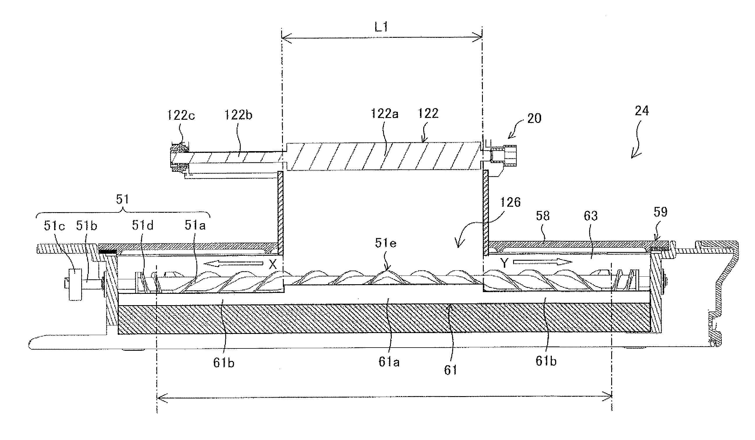
The present invention aims to provide a developing device that can evenly disperse toner supplied from a toner supply device, even if the length of the toner supply opening is reduced in the axial direction of the developing roller due to downsizing of the toner supply device and an image forming apparatus employing the developing device. This will prevent unevenness in toner concentration and ensure stable and even image concentration.

Problems solved by technology

The stirring causes friction between the toner and the carrier.
Further, speeding up and downsizing have been recently required for the image forming apparatus.

Method used


Image

  • Developing device and image forming apparatus
  • Developing device and image forming apparatus
  • Developing device and image forming apparatus

Examples


Embodiment Construction

[0023]The following describes an embodiment of the present invention with reference to drawings.

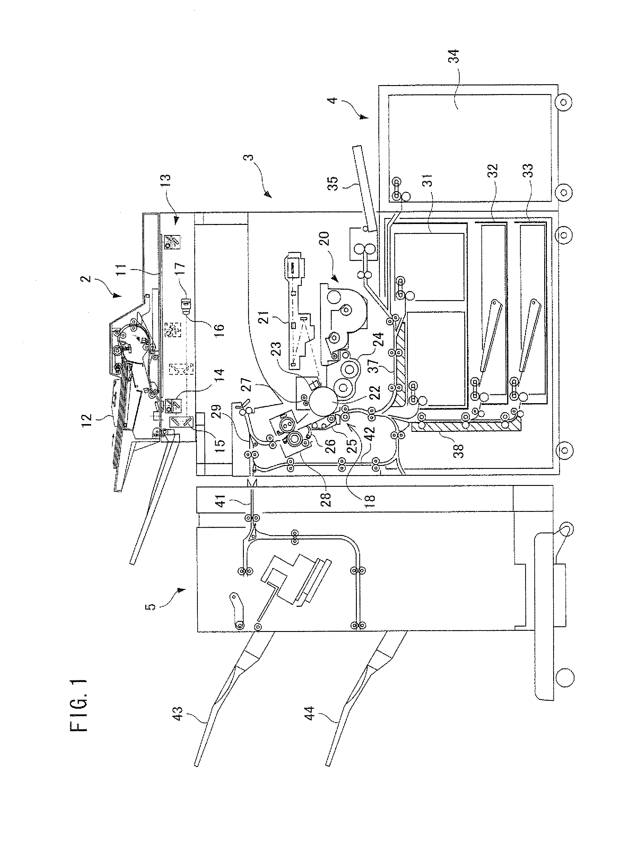
[0024]FIG. 1 is a longitudinal cross-sectional view of an image forming apparatus in accordance with an embodiment of the present invention.

[0025]An image forming apparatus includes an image reading section 2, an image forming section 3, and a paper feeding section 4, and a paper output section 5, as shown in FIG. 1.

[0026]The image reading section 2 includes a scanner platen made of a transparent glass, a reverse automatic document feeder (RADF) 12 for automatically supplying a document onto the scanner platen 11 such that both sides of the document are read, and a document image reading unit, that is, a scanner unit 13 for scanning and reading an image of the document placed on the scanner platen 11.

[0027]The reverse automatic document feeder 12 automatically feeds, one by one, a plurality of documents placed on a document tray onto the scanner platen 11 of the scanner unit 13. The rever...


PUM


Abstract

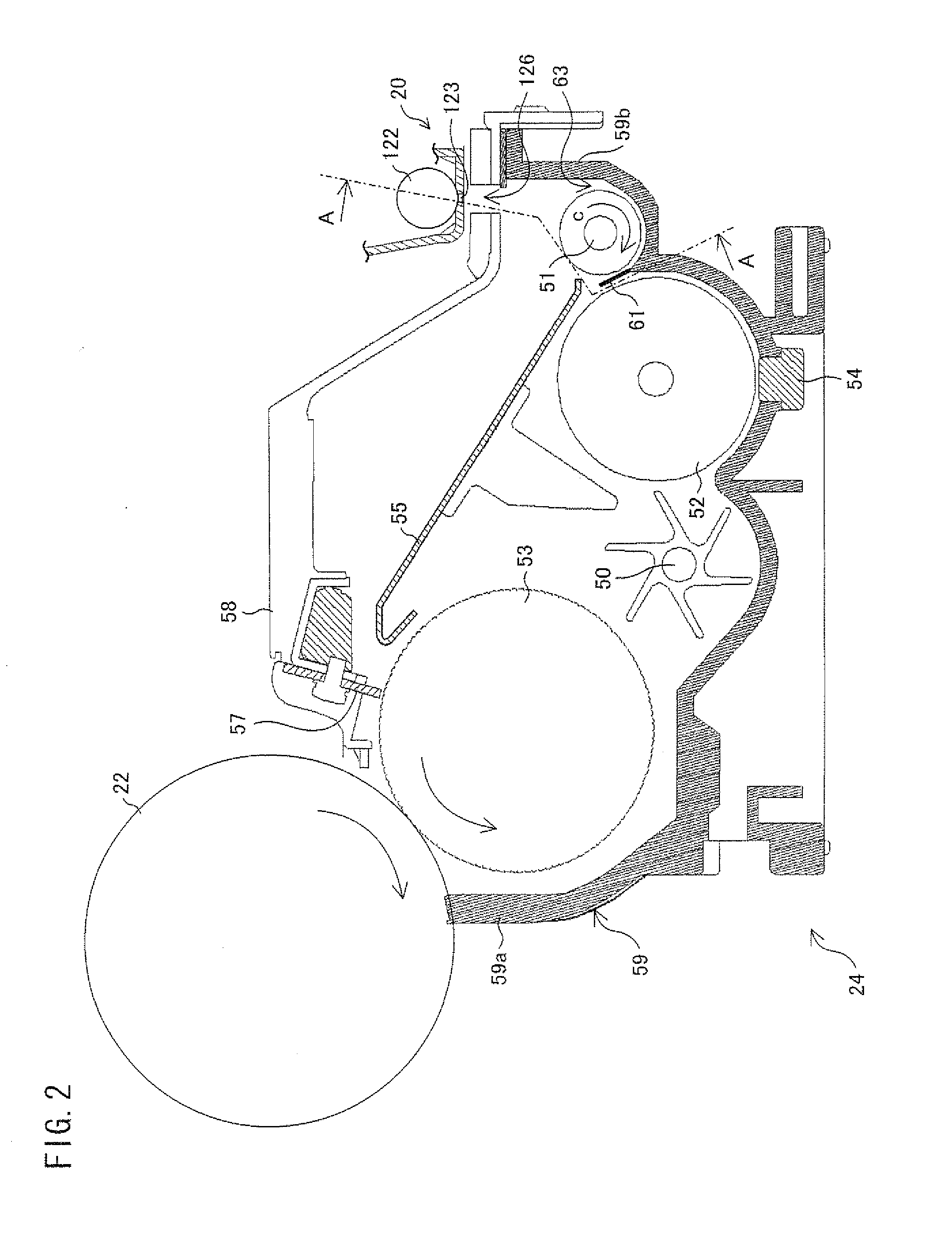
A developing device includes a developing tank, a developing roller, a supply toner carrying path, and a supply toner diffusion screw. A partition board provided parallel to the developing roller in the developing tank has, in an axial direction of the supply toner diffusion screw, a first region and a second region lower than the first region. The first region is located so as to face a region perpendicularly below a toner supply opening, and the second region is located so as not to face the region perpendicularly below the toner supply opening.

Description

[0001]This Nonprovisional application claims priority under 35 U.S.C. §119(a) on Patent Application No. 2010-197955 filed in Japan on Sep. 3, 2010, the entire contents of which are hereby incorporated by reference.TECHNICAL FIELD[0002]The present invention relates to (i) a developing device that employs a two-component developer containing toner and a magnetic carrier and (ii) an image forming apparatus employing the developing device. The present invention is for use in an image forming apparatus, such as an electrostatic copying machine, a laser printer or a facsimile, that forms an image by use of toner by means of an electrophotographic printing method.BACKGROUND ART[0003]Conventionally, electrophotographic image forming apparatuses, such as a copying machine, a printer and a facsimile, have been known. In such electrophotographic image forming apparatuses, an electrostatic latent image is formed on a surface of a photoreceptor drum, the electrostatic latent image is developed b...

Claims


Application Information

Patent Timeline
Patent Type & Authority Applications(United States)
IPC IPC(8): G03G15/08
CPCG03G15/0808
Inventor MAEHARA, HIROYOSHIKIMURA, TAKAHIKOKUBOTA, HIROSHISUDO, TERUYOSHI
Owner SHARP KK
Learn More