
Maintaining power through a data transmission cable

a data transmission cable and main power technology, applied in the direction of data processing power supply, liquid/fluent solid measurement, instruments, etc., can solve the problems of large and unpredictable current drawn by the components of variable load 106, significant unnecessary waste of power, and inability to supply power

Active Publication Date: 2012-03-08
TEXAS INSTR INC
View PDF17 Cites 36 Cited by
  • Summary
  • Abstract
  • Description
  • Claims
  • Application Information

AI Technical Summary

Benefits of technology

The patent text describes a system for supplying power and data to electronic devices through data transmission cables. The system uses a power over Ethernet (PoE) standard to provide power to the devices. The devices can enter a low power mode to save power, but the system needs to maintain a minimum current draw to ensure that the devices are still present and can communicate with the system. The patent describes a circuitry component called an MPS (Maintain Power Signature) that helps to meet this requirement. The MPS circuitry includes a fixed load and a variable load that draws current in the low power mode. The variable load can include components like an LED to indicate the low power mode, and other circuitry that may come out of the low power mode when needed. The system can also use the Ethernet standards to connect non-PoE devices to the system, but the non-PoE devices should not be connected to the same port as a PoE device, as this could damage the non-PoE device. The patent aims to minimize power consumption and cost by allowing the PoE PD to enter a low power mode at various times.

Problems solved by technology

In this case, it is undesirable to supply power through the cable to the non-PoE device, because the electrical power could damage the non-PoE device.
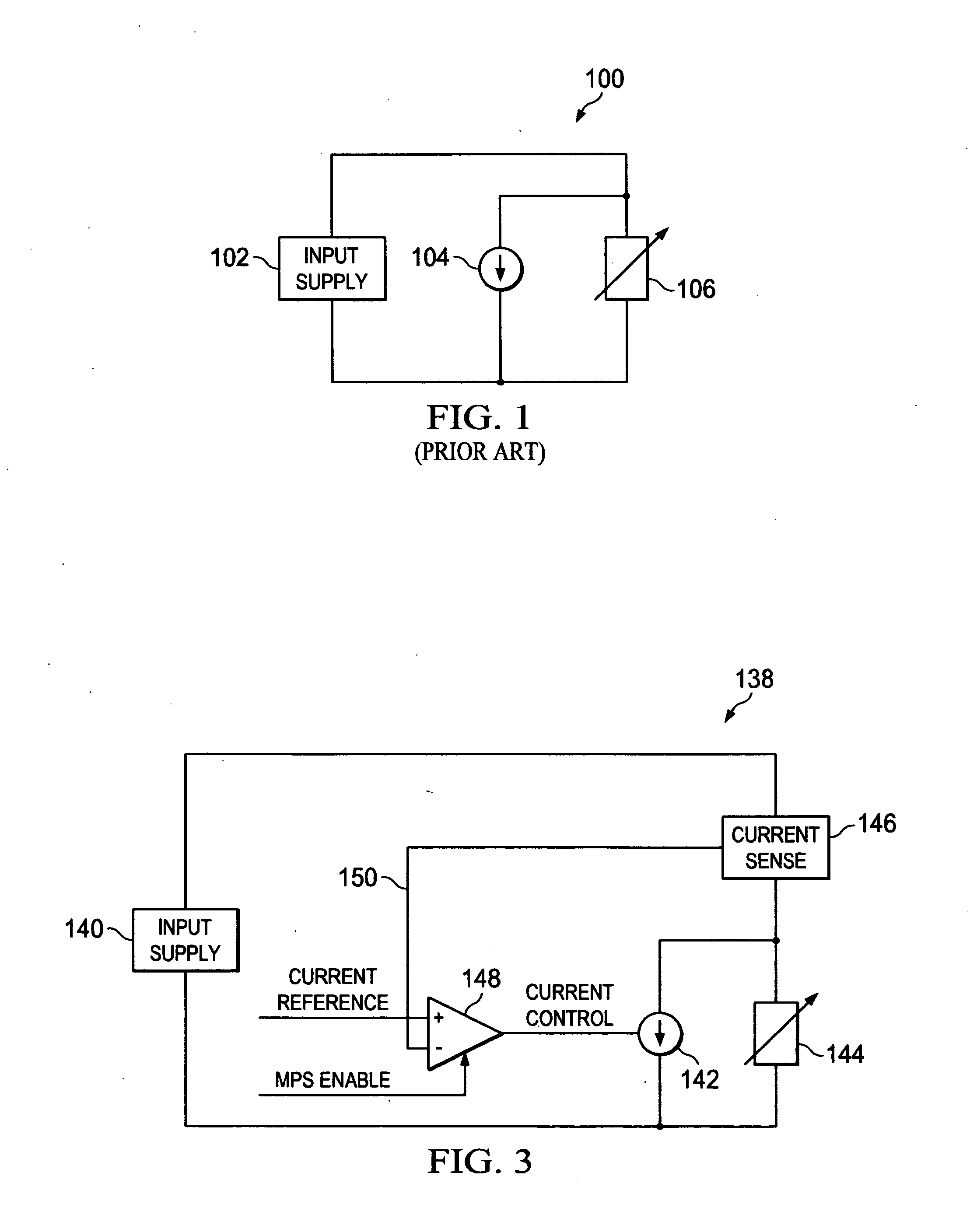
In fact, the current drawn by the components of the variable load 106 may vary widely and unpredictably, due to a variety of causes.
As a result, there may be significant unnecessary waste of power by the combined operation of the variable load 106 and the fixed load 104.
This waste of power renders the green or low power mode highly inefficient.

Method used


Image

  • Maintaining power through a data transmission cable
  • Maintaining power through a data transmission cable
  • Maintaining power through a data transmission cable

Examples


Embodiment Construction

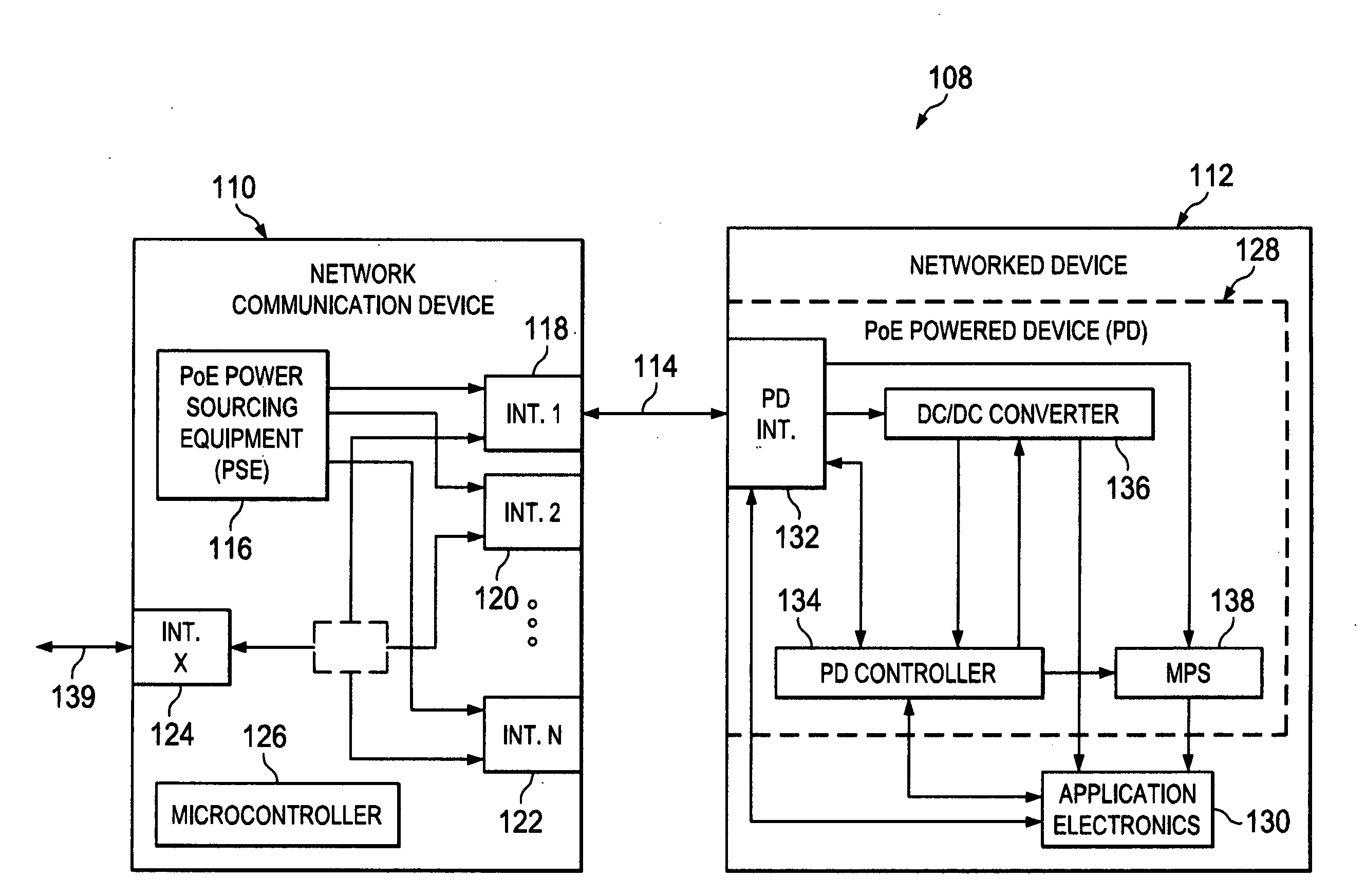
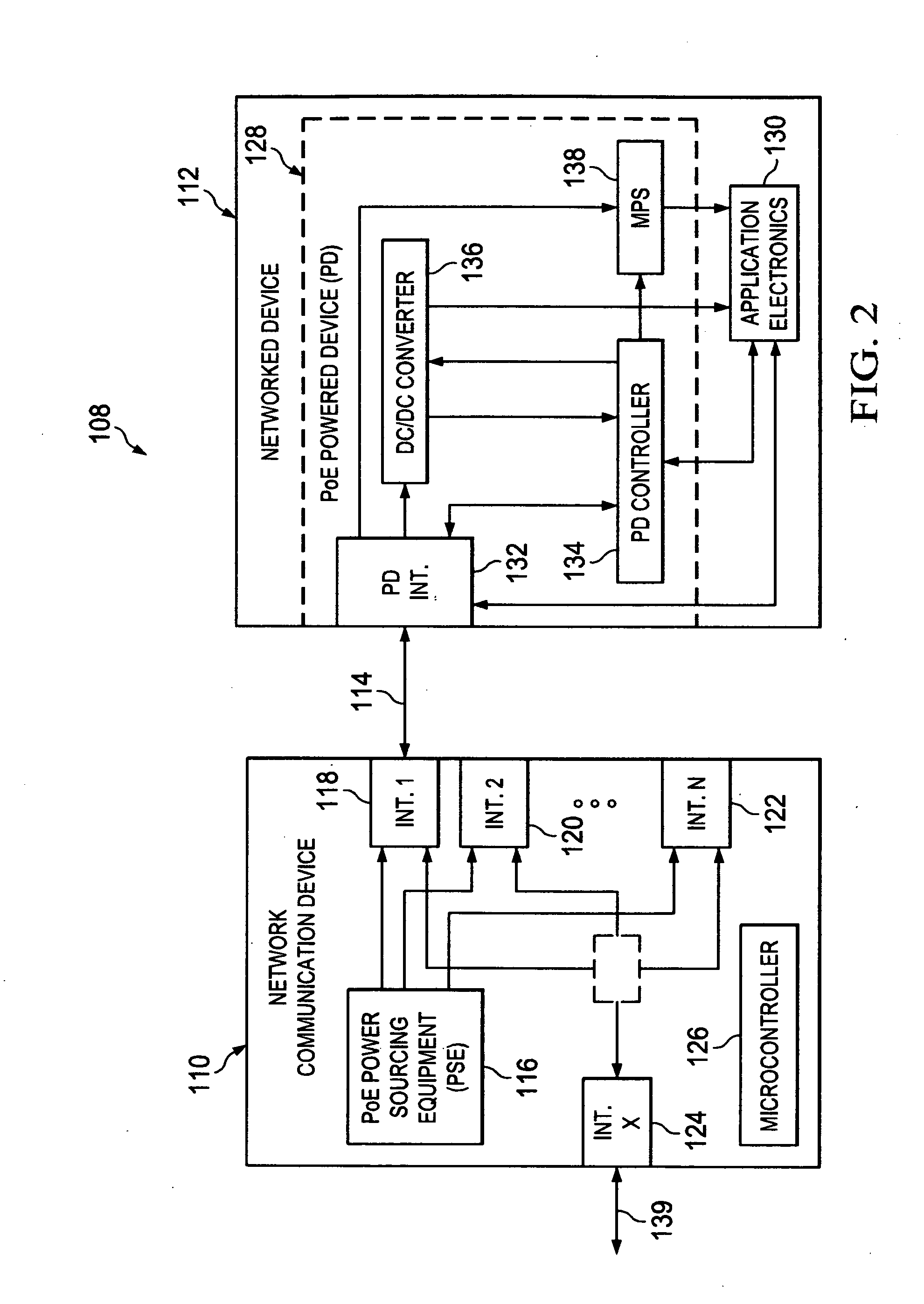
[0019]FIG. 2 shows a simplified example of an Ethernet system 108 with Power over Ethernet (PoE) that generally includes a Network Communication Device 110 (e.g. a switch, router, hub, etc.), and one or more Networked Devices 112 (e.g. an internet phone, a networked camera, a wireless access point, etc.) connected by one or more Ethernet cables 114. The Network Communication Device 110 generally includes a PSE 116, several ports or interfaces (Int. 1, Int. 2 . . . Int. N and Int. X) 118, 120, 122 and 124 and a microcontroller 126, among other possible components that depend on the type of Ethernet device the Network Communication Device 110 is. The Networked Device 112 generally includes a PD 128 and Application Electronics 130. The PD 128 generally includes a port or interface (PD Int.) 132, a PD controller 134, a DC / DC converter (or other appropriate type of power converter) 136 and an MPS circuitry 138.

[0020]The Networked Device 112 can enter a low power mode (e.g. a sleep, hiber...


PUM


Abstract

A powered device receives electrical power through a data transmission cable from a power supplying device that monitors a load on the data transmission cable and turns off the power to the load if the load is outside of a range. The powered device draws a first current at least part of a time during which the powered device is in a low power mode. The powered device is operable during the low power mode to draw a second current. And the powered device increases and decreases the second current to maintain a sum of the first current and the second current, or a level of a current into the powered device, at least at a minimum level for at least a portion of a cycle time.

Description

BACKGROUND OF THE INVENTION[0001]Many electronic devices send and receive streams of data through data transmission cables according to a wide variety of communication standards. Like all electronic devices, such devices require electrical power in order to operate. In some situations, however, it may be desirable to place such a device, and extend a data transmission cable to it, in a location where an electrical power source is not readily available. It is advantageous in many such cases, therefore, to use the data transmission cable to supply the electrical power to the electronic device. In this manner, it is not necessary to install a separate power outlet near the electronic device, and greater flexibility is achieved in the selection of locations for such devices, such as internet phones, cameras and wireless access points.[0002]Some example systems for transmitting both data and power over conventional data transmission cables include devices defined by the “Power over Ether...

Claims


Application Information

Patent Timeline
Patent Type & Authority Applications(United States)
IPC IPC(8): G06F1/32G06F11/30
CPCG06F1/266
Inventor BUHARI, RIAZDEENPATOKA, MARTIN H.
Owner TEXAS INSTR INC
Learn More