Sensor

Active Publication Date: 2012-03-15
GE INFRASTRUCTURE SENSING
View PDF8 Cites 2 Cited by
  • Summary
  • Abstract
  • Description
  • Claims
  • Application Information

AI Technical Summary

Benefits of technology

[0010]By attaching each end of the beams to a support at more than one point, for example two points, the moments and reaction forces to which the support is subjected may be balanc

Problems solved by technology

Furthermore, the distortion of the diaphragm 5 caused by the moments 7 to which the mesas 4 are subjected also causes distortion of the beams 3 degrading the measurement of the beam position, further reducing the precision of measurements.
This reduction in the precision of measuremen

Method used


Image

  • Sensor
  • Sensor
  • Sensor

Examples


Example

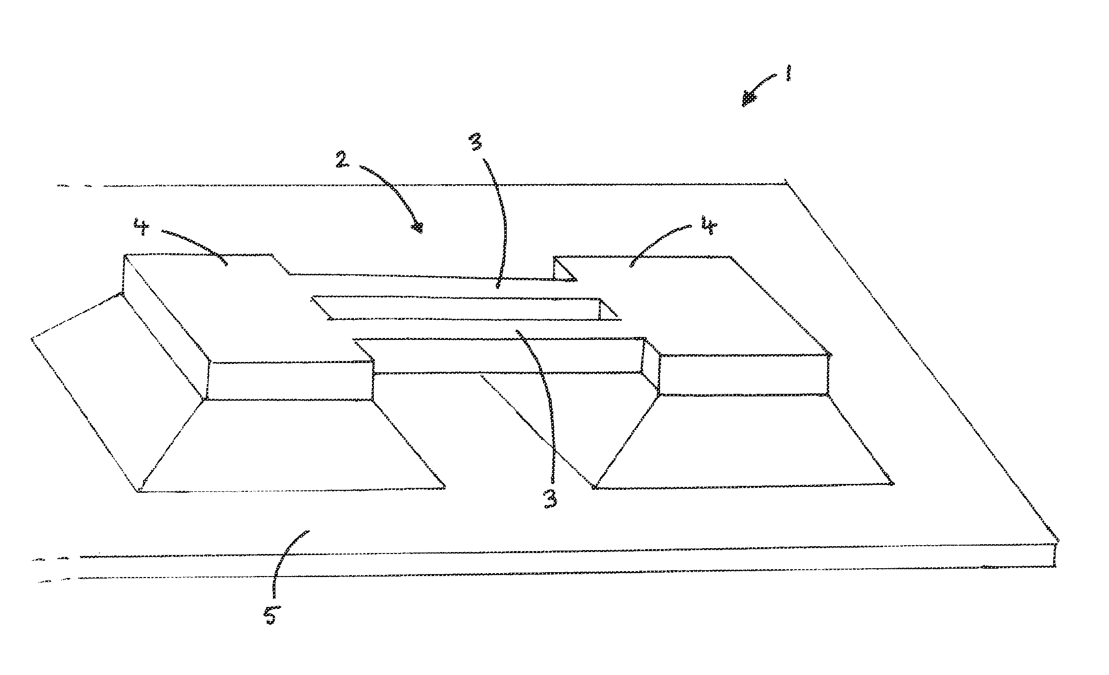
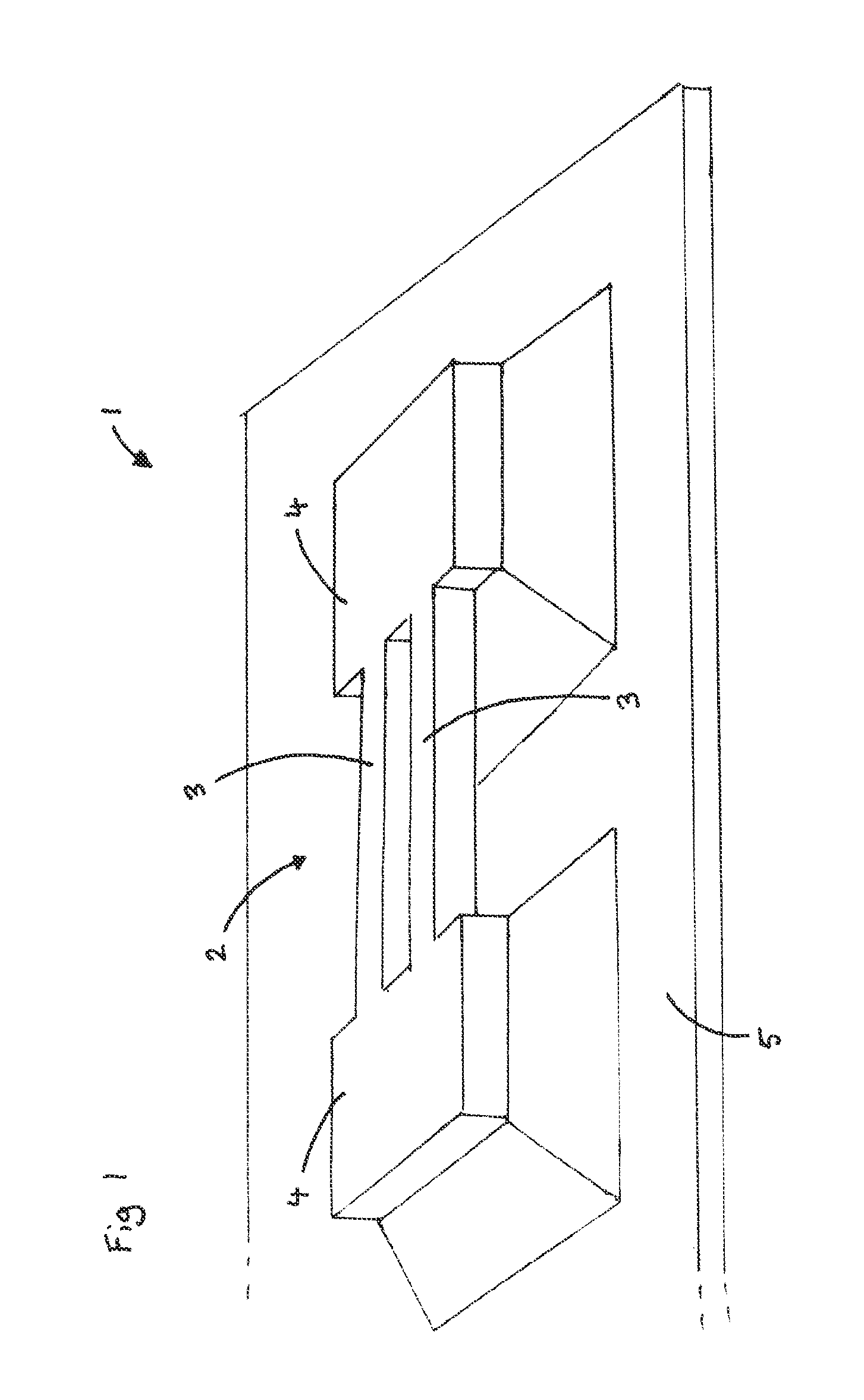
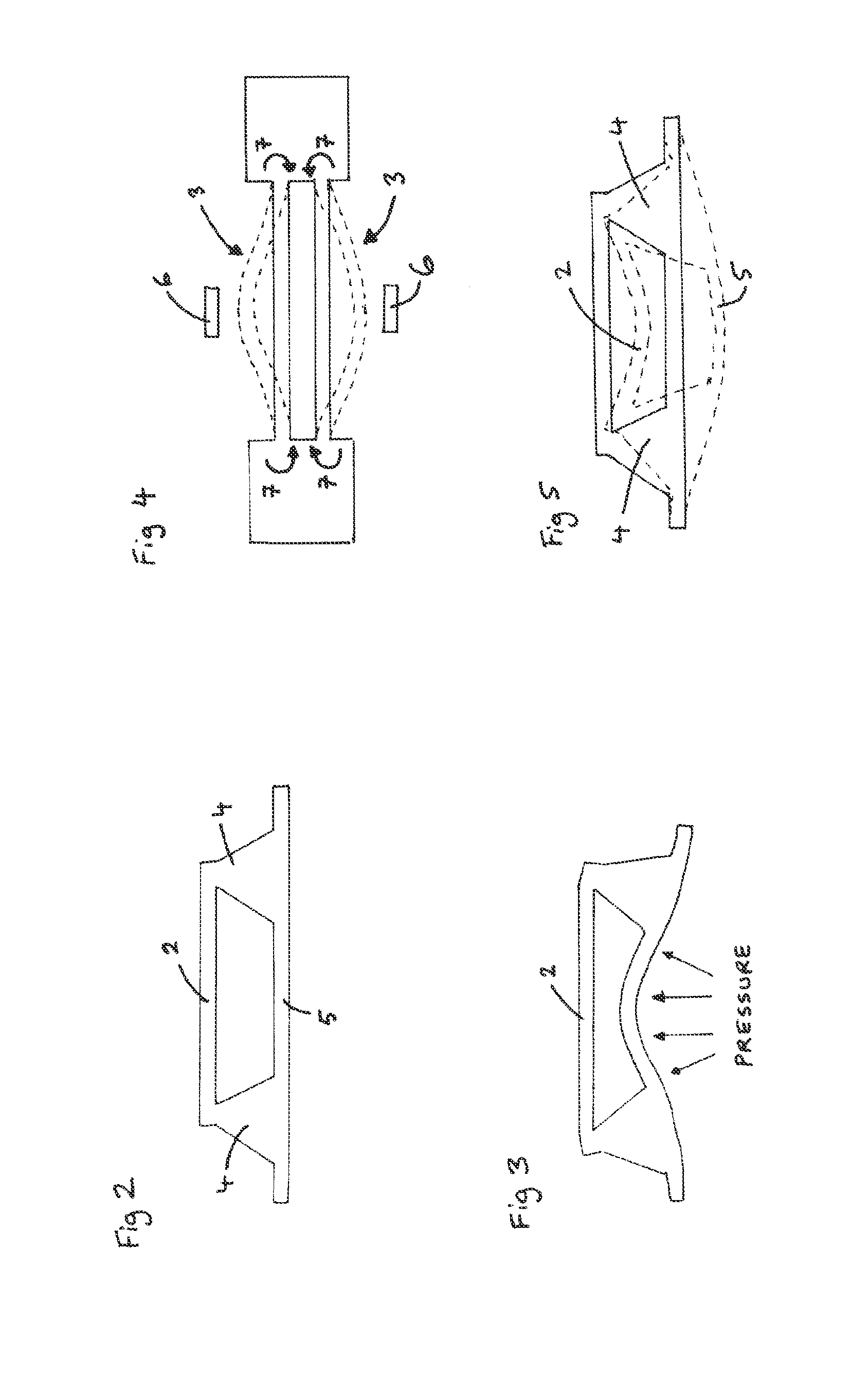
[0018]FIG. 6 illustrates a first embodiment of a resonant sensor 10 of the present disclosure. A diaphragm 11, shown by dashed lines is provided to be exposed to a fluid, generally to determine the pressure of the fluid. The diaphragm 11 preferably comprises silicon. The diaphragm 11 is provided with two supports or mesas 12. The mesas 12 are preferably integrally formed on the diaphragm 11. A resonator 13 is suspended between the two mesas 12. In this example, the resonator 13 compresses two beams 14, with the end portion of each beam being attached to a mesa 12 at more than one point, in this example at two points 15. As can be seen from the curved arrows 16 on the left hand side of FIG. 6 illustrating the moments produced by the movement of the beams 14, the overall reaction forces 17 to which each mesa 12 is subjected are balanced. As a result, the tops of the mesas 12 are not distorted, or at least are distorted by a far lesser extent than if the ends of each beam were to be mo...


PUM


Abstract

A resonant sensor is disclosed which may be arranged to measure the pressure of a fluid. The resonant sensor comprises a diaphragm which may be exposed to a fluid; two supports provided on the diaphragm and a resonator having at least two beams with each beam being suspended between the two supports. The ends of each beam are attached to a corresponding support at more than one point. By attaching each end of the beams to a support at more than one point, the moments and reaction forces to which the support is subjected may be balanced so that distortion of the support and diaphragm due to vibration of the resonator beams is reduced. Consequently, the resonant sensor is able to provide more precise measurements.

Description

CROSS-REFERENCE TO RELATED APPLICATIONS[0001]This is a national stage application under 35 U.S.C. §371(c) of prior-filed, co-pending PCT patent application serial number PCT / GB2010 / 0050783, filed on May 13, 2010, which claims priority to a British patent application serial number 0908794.1, filed on May 21, 2009, each of which is hereby incorporated by reference in its entirety.BACKGROUND OF THE INVENTION[0002]1. Field of the Invention[0003]The present disclosure relates to a sensor, in particular a resonant sensor which may be arranged to measure the pressure of a fluid.[0004]2. Description of Related Art[0005]Resonant sensors have a diaphragm, typically manufactured from silicon, which is exposed to a fluid, the pressure of which is to be measured. Silicon is typically used for the diaphragm as it has a very repeatable elastic behaviour. Variations in pressure of the fluid exposed to the diaphragm cause the diaphragm to flex or deform in accordance with the pressure of the fluid. ...

Claims


Application Information

Patent Timeline
IPC IPC(8): G01L11/00
CPCG01L9/0022G01L9/0013
Inventor KINNELL, PETER KEN
Owner GE INFRASTRUCTURE SENSING
Why Eureka
Try Eureka