Automated stick-frame system

a stick-frame system and stick-frame technology, applied in metal sawing accessories, metal sawing devices, manufacturing tools, etc., can solve the problems of time-consuming and costly processes

Inactive Publication Date: 2012-03-15
DUNMOW SYST CORP
View PDF0 Cites 26 Cited by
  • Summary
  • Abstract
  • Description
  • Claims
  • Application Information

AI Technical Summary

Problems solved by technology

A problem arises in using traditional construction techniques as the process can be time consuming and costly due to the high level of manual labor involved in fabricating the lumber to size and the large amount of scrap incurred in the construction process.

Method used


Image

  • Automated stick-frame system
  • Automated stick-frame system
  • Automated stick-frame system

Examples


Embodiment Construction

)

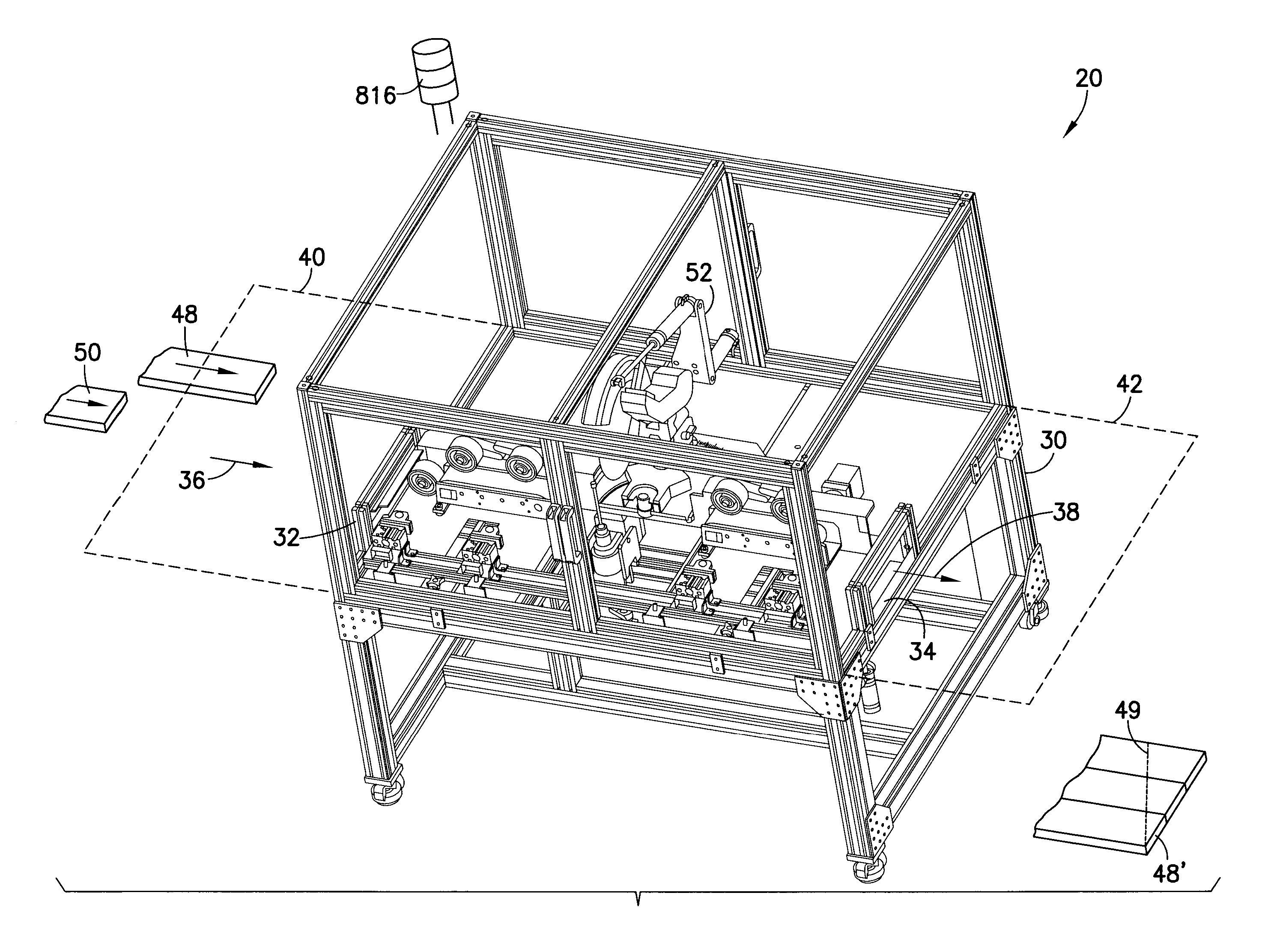
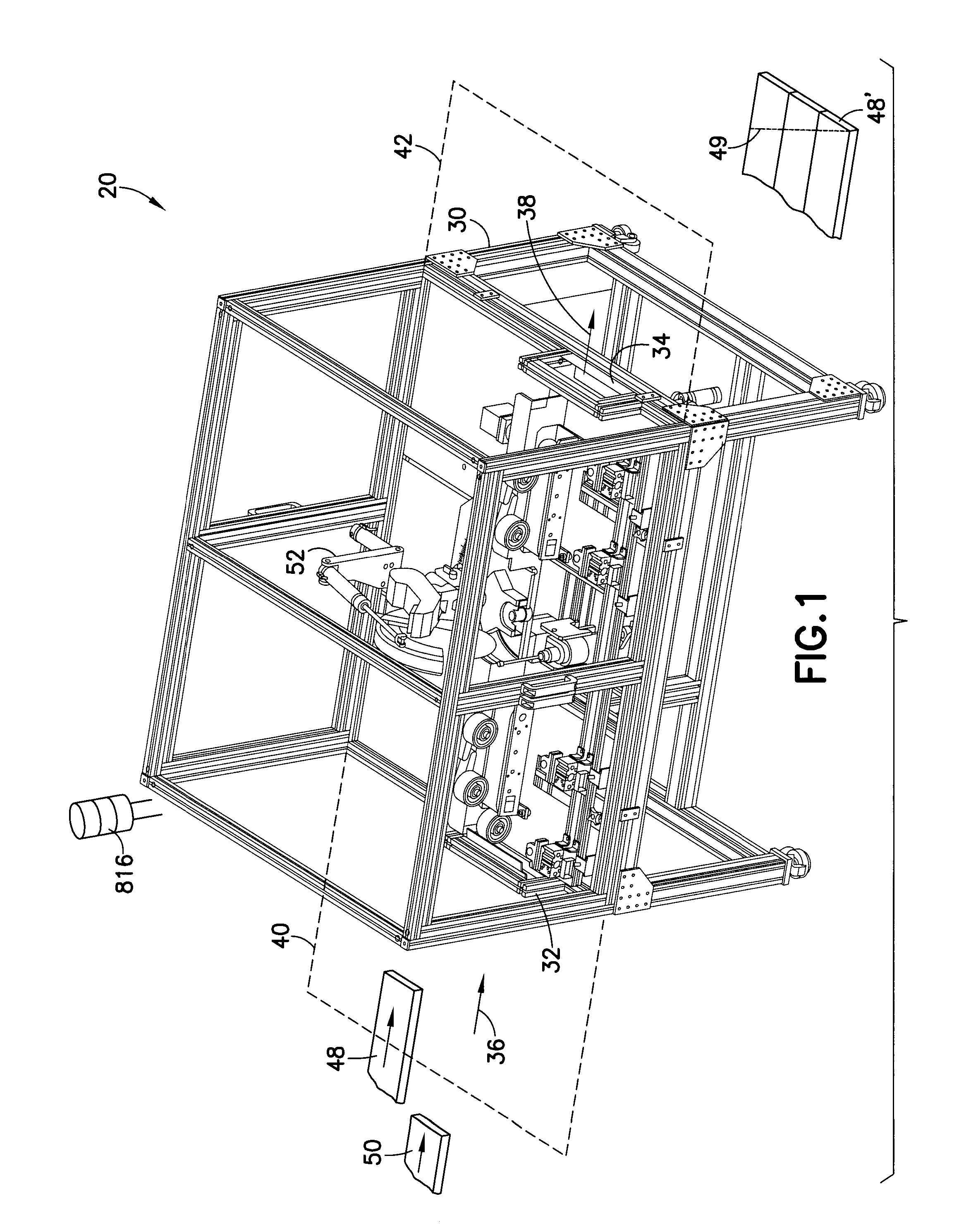
[0040]Referring to FIG. 1, there is shown, an isometric view of an automated stick system 20 capable of cutting framing or trim components or otherwise for use in construction or otherwise incorporating features in accordance with an exemplary embodiment. Although the present invention will be described with reference to the embodiments shown in the drawings, it should be understood that the present invention can be embodied in many alternate forms of embodiments. In addition, any suitable size, shape or type of elements or materials could be used.

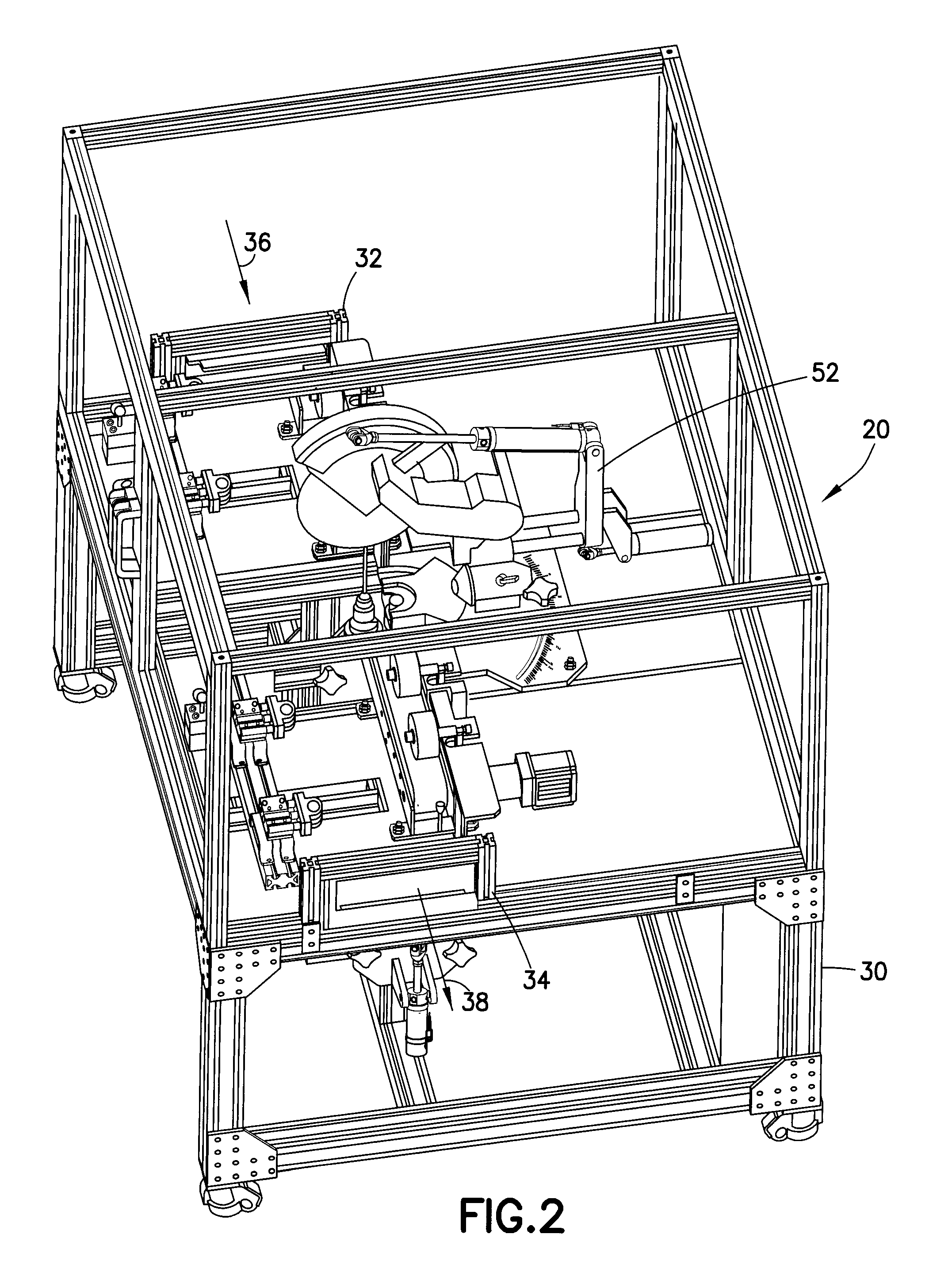
[0041]Referring also to FIG. 2 there is shown an isometric view of an automated stick-frame system 20. In the embodiment shown, stick machine or system 20 may comprise frame 30 having infeed portion 32 and outfeed portion 34. Lumber is fed in a direction 36 through infeed portion 32, the lumber processed and the lumber exits system 20 in direction 38 through outfeed portion 34. An in-feed drive, including for example in-feed conveyor 40, ...


PUM

PropertyMeasurementUnit
angleaaaaaaaaaa
angleaaaaaaaaaa
angleaaaaaaaaaa

Abstract

A automated stick cutting system is provided adapted to produce stick-frame construction components from material for building construction. The automated stick cutting system has a frame having an in-feed portion and an out-feed portion. A saw is adapted to cut the material, the saw coupled to the frame. An in-feed drive is coupled to the frame, the in-feed drive adapted to accept the material from the in-feed portion and feed the material to the saw. A position detector is coupled to the frame, the position detector adapted to track a position of the material relative to the in-feed drive. An out-feed drive is adapted to accept the material uncut from the in-feed drive, the out-feed drive adapted to accept the material cut from the saw and feed cut material to the out-feed portion. An edge detector is adapted to detect a leading edge of the material when being fed to the saw by the in-feed drive. The position detector and the edge detector cooperate with operation of the saw to meter lengths of the material through the in-feed drive and to cut a predetermined length of the material with the saw.

Description

RELATED APPLICATIONS[0001]This application claims priority from U.S. Provisional Patent Application Ser. No. 61 / 362,139 Filed Jul. 7, 2010 entitled “AUTOMATED STICK-FRAME SYSTEM” which is hereby incorporated by reference herein in its entirety.BACKGROUND[0002]1. Field[0003]The disclosed embodiments relate to an automated stick system and, more particularly, to an automated machine adapted to produce stick-frame construction components.[0004]2. Brief Description of Earlier Developments[0005]Home construction projects often may involve many different forms of carpentry, from framing carpentry through finish carpentry. Typical construction involves a general contractor hiring carpenters by the job or by the hour to complete framing, trim or finish operations. To complete the job, detailed construction plans are provided to the carpenters from which the carpenter provides lumber, for example, framing lumber, finish mill work or other lumber suitable for the type of construction, fastene...

Claims


Application Information

Patent Timeline
Patent Type & Authority Applications(United States)
IPC IPC(8): B27B5/29
CPCB23D45/048B23D45/143B23D59/008B23D47/10B23D59/001B23D47/042Y10T83/531
Inventor HINSHAW, FOSTER D.FOSNIGHT, WILLIAM J.
Owner DUNMOW SYST CORP
Why Eureka
Try Eureka