Microscale fluid delivery system

a fluid delivery system and micro-scale technology, applied in the direction of basic electric elements, cleaning processes and utensils, liquid cleaning, etc., can solve the problems of particle not seeing this energy threshold, boundary layer particle thickness cannot be completely eliminated, etc., to enhance material removal, enhance material transfer, and enhance material transfer

Inactive Publication Date: 2012-03-15
GRAY DONALD
View PDF4 Cites 43 Cited by
  • Summary
  • Abstract
  • Description
  • Claims
  • Application Information

AI Technical Summary

Benefits of technology

[0008]Vacuum Cavitational Streaming (VCS) is a new technology presently being used to enhance the transfer of material to or from the surface of a solid. The process is accomplished by reducing the total pressure in a controlled environmental chamber containing a part submerged in a liquid to below the vapor pressure of the liquid. The process results in the formation of vapor bubbles at the solid part's surface where typically nucleation sites for bubble formation can be found in the form of imperfections, crevices or foreign particle material. The return of the chamber to pressures at or above the liquid vapor pressure collapses these vapor bubbles releasing energy at the solid surface. The energy disrupts the fluid boundary layer near the solid surface and enhances the removal of material from the surface or continuously replenishes the liquid within the boundary layer to produce a high concentration of material being transferred to the surface. Since the turbulent disruption begins at the solid surface, the process is unaffected by the size of the fluid boundary layer, a major resistance region for conventional forced convective mass transfer or ultrasonic processes.

Problems solved by technology

Increasing the fluid velocity reduces the boundary layer thickness and thus enhances the transfer rate, however, the boundary layer can never be totally eliminated.
If the boundary layer is large as compared to the particle of insoluble material, then the particle may never see this energy threshold and no solid removal will be accomplished.
The surface process is slowed due to the often large diffusion path required to reach the surface to be treated.

Method used


Image

  • Microscale fluid delivery system
  • Microscale fluid delivery system
  • Microscale fluid delivery system

Examples


Embodiment Construction

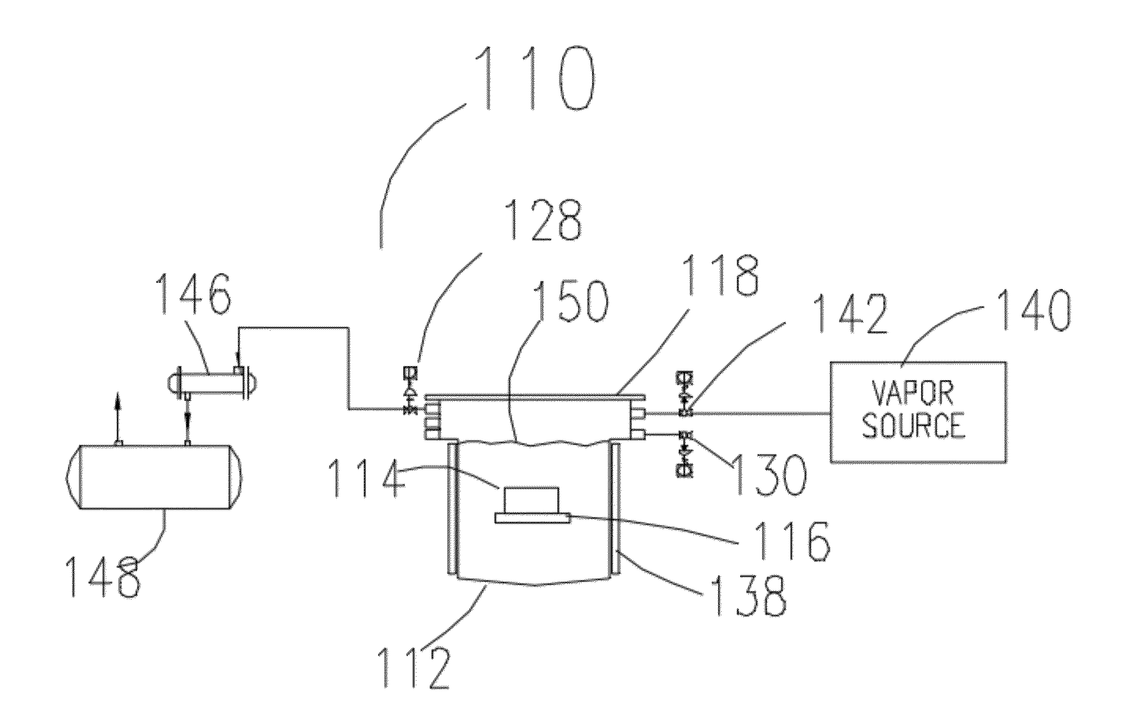
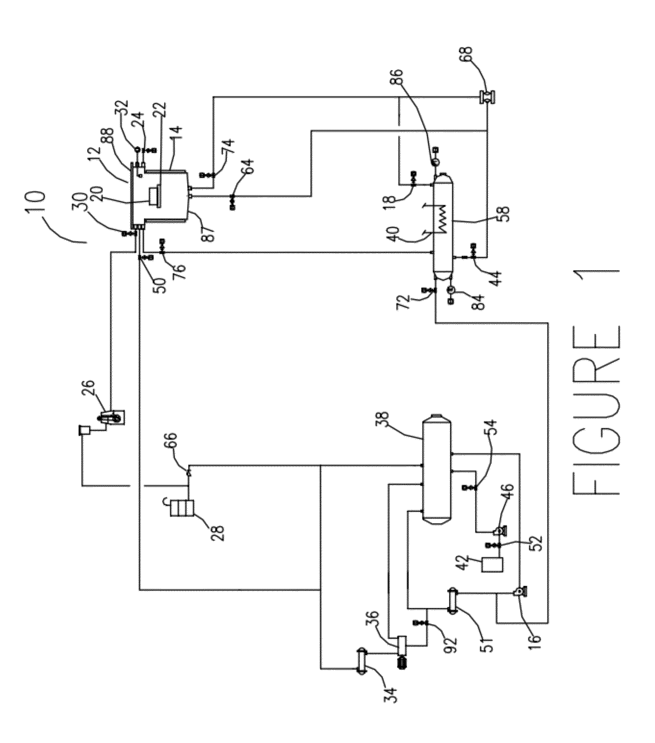
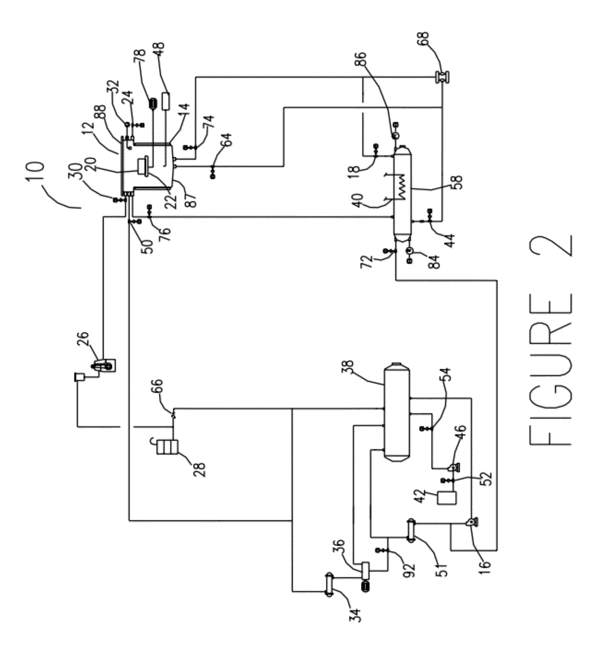
[0053]Referring now to the drawings, the solvent and aqueous decompression processing system of the present invention is illustrated and generally indicated at 10 in FIG. 1.

[0054]In FIG. 1, the system 10 for implementing the teachings of this invention includes a main vacuum cavitational streaming (VCS) chamber generally indicated at 12 that may or may not be heated. The main VCS chamber 12 includes a main body portion 87 and a lid 88. In the preferred embodiment, the main body portion 87 of the VCS chamber 12 has an electric heat blanket 14. Other options for heating the chamber 12 include steam, or other heat transfer fluids, such as oil or hot water in an external jacket, plate coils or external pipe welded or soldered to the chamber. The system 10 further includes a solvent source generally indicated at 42, a solvent holding tank generally indicated at 38, and a heated solvent vessel generally indicated at 58. Other component parts of the system 10 will be described in connectio...


PUM


Abstract

A microscale fluid delivery system has a method of addition and removal of fluids to the internals of solids is in an enclosed system. The system includes a processing chamber comprising the steps of submerging the object within the chamber in a fluid, isolating the chamber, reducing the pressure to form vapor bubbles on the object's internal surfaces, increasing the pressure to introduce fluid to the object's internal surfaces, and repeating the decrease and increase in pressure until the object is fully processed.

Description

CROSS REFERENCE TO RELATED APPLICATION[0001]This application is related to and claims priority from earlier filed U.S. Non-Provisional patent application Ser. No. 11 / 280,021 filed Nov. 16, 2005, the entire contents of which is incorporated herein by reference.BACKGROUND OF THE INVENTION[0002]The invention provides a means for transferring a solution or solvent into and out of tight areas in order to deliver this fluid to the area for surface processing. The invention allows for the delivery of fresh bulk fluid to these areas so as to increase the rate of chemical interaction with the solid surfaces being treated.[0003]The transfer of material to or from a solid surface submerged within a liquid encounters most of the resistance to mass transfer within the fluid boundary layer surrounding the solid surface. It is within this region that the fluid velocity used to convectively transfer either dislodged or dissolved material away from the object into the bulk fluid (used as the cleaner...

Claims


Application Information

Patent Timeline
Patent Type & Authority Applications(United States)
IPC IPC(8): B08B9/20
CPCB08B3/12H01L21/67057H01L21/67051H01L21/67017
Inventor GRAY, DONALD
Owner GRAY DONALD
Why Eureka
Try Eureka