Pneumatic tire

a technology of pneumatic tires and treads, applied in the field of pneumatic tires, can solve the problems of reducing the rigidity of treads, affecting steering stability and braking ability, and affecting the stability of steering, so as to suppress the decline in tread rigidity, improve the cubic capacity of closed sipes, and enhance water absorption.

Active Publication Date: 2012-03-15
THE YOKOHAMA RUBBER CO LTD
View PDF7 Cites 6 Cited by
  • Summary
  • Abstract
  • Description
  • Claims
  • Application Information

AI Technical Summary

Benefits of technology

[0005]The present technology provides a pneumatic tire configured so that water absorption can be enhanced while suppressing a decline in tread rigidity in a tire having a sipe formed in a tread surface; braking performance on ice can be enhanced while maintaining steering stability performance; and releaseability from a mold is not hindered.
[0011]According to the present technology described above, a closed sipe is provided in a tread surface that is centered on a small hole extending in a tire radial direction, and has a plurality of cuts extending in a radiation direction from the small hole and that terminate in a land portion. The cuts are provided with a twist in a depth direction centered on the small hole, and a twist angle from a top surface to a bottom surface of the land portion is not less than 10° and less than 135° . Therefore, water absorption can be enhanced due to an increase in the cubic capacity of the closed sipe while suppressing a decline in tread rigidity without hindering releaseability from a mold; and braking performance on ice can be enhanced while maintaining steering stability when traveling on dry and wet road surfaces.
[0012]Moreover, because the diameter of the inscribed circle of the small hole located in a center portion of the closed sipe is configured so as to be greater than the thickness of the cuts, the flow of water into the small hole when traveling on icy road surfaces is facilitated, and the water that flows into the small hole can be efficiently dispersed toward each of the cuts. This leads to rapid and efficient water absorption.

Problems solved by technology

However, if an excessive number of sipes are disposed in the tread surface, the tread rigidity will decline, leading to steering stability and braking ability being negatively affected.
However, in the case of Japanese Unexamined Patent Application No.
H9-263111A, while the water absorption of the tread surface is enhanced to a certain degree, there is a limitation in that it becomes difficult to maintain steering stability if further enhancements of the water absorption are attempted.
Additionally, in the case of Japanese Unexamined Patent Application Publication No. 2006-27306A, due to the twist angle being set to a size reaching 135° and greater, there are problems such as releaseability from a mold after the tire is vulcanization molded being negatively affected and the tread surface becoming easily damageable.

Method used


Image

  • Pneumatic tire
  • Pneumatic tire
  • Pneumatic tire

Examples


examples

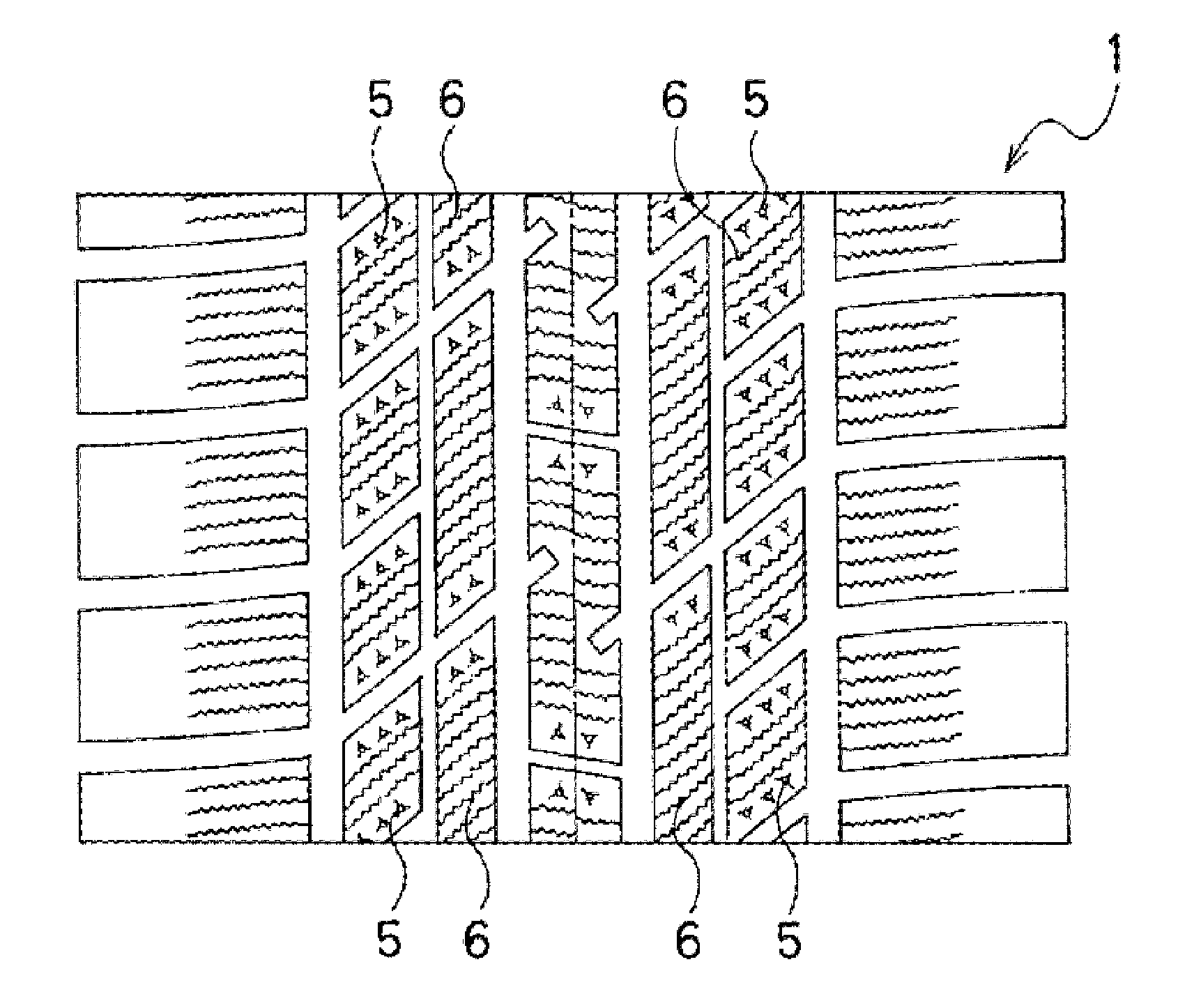
[0038]Tires of the present technology (Working Examples 1 to 8) and comparison tires (Comparative Examples 1 to 4) were fabricated having a tire size of 195 / 65R15 91Q and the tire pattern illustrated in FIG. 6. Note that in FIG. 6, an example is illustrated in which three of the cuts 4 of the closed sipe 5 are provided.

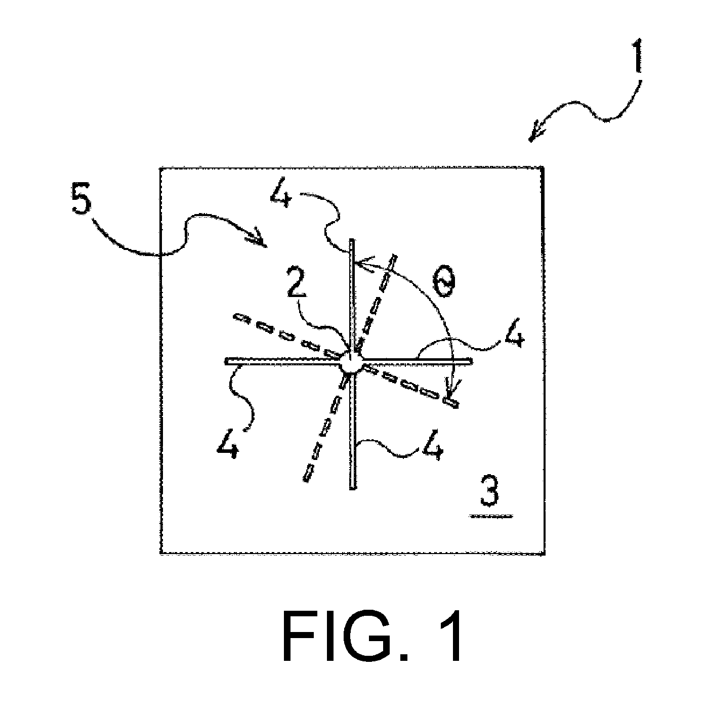
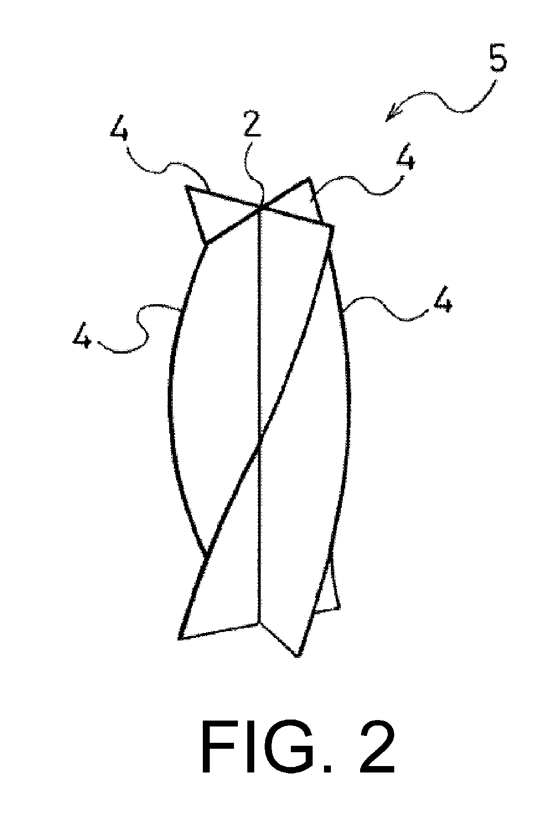
[0039]In the Working Examples, the closed sipe 5 had a form wherein the cuts 4 extend in a radiation direction from a center axis that extends in the tire radial direction, and terminate in the land portion; and the small hole 2 was formed on the center axis. Each of the closed sipes 5 had a common depth of 7 mm and each of the cuts 4 had a common thickness w of 0.5 mm. Tires of Working Examples 1 to 8 and Comparative Examples 1 and 2 were fabricated wherein the number of cuts 4, the twist angle of the cuts 4, the diameter d of the inscribed circle of the small hole 2, d / w, the presence of the sipe 6 extending in the tire width direction, and whether the closed sipe 5...


PUM


Abstract

A pneumatic tire including a closed sipe 5 formed in a tread surface 1 that includes a small hole 2 extending along a tire radial direction and a plurality of cuts 4 extending in a radiation direction from the small hole 2 and that terminating in a land portion 3. A diameter of an inscribed circle of the small hole 2 is greater than a thickness of the cuts 4. The cuts 4 are provided with a twist in a depth direction centered on the small hole 2, and a twist angle θ from a top surface to a bottom surface of the land portion 3 is not less than 10° and less than 135°.

Description

TECHNICAL FIELD[0001]The present technology relates to a pneumatic tire, and particularly relates to a pneumatic tire configured so that braking performance when traveling on icy road surfaces is enhanced without hindering the steering stability of a tire having sipes formed in a tread surface thereof.BACKGROUND ART[0002]Sipes are commonly provided in a tread surface in order to enhance water absorption in order to enhance traveling performance on wet road surfaces and icy and snowy road surfaces. However, if an excessive number of sipes are disposed in the tread surface, the tread rigidity will decline, leading to steering stability and braking ability being negatively affected. Therefore, conventionally, various technologies have been proposed regarding the form and arrangement of the sipe (e.g. see Japanese Unexamined Patent Application No. H9-263111A and Japanese Unexamined Patent Application Publication No. 2006-27306A).[0003]Of these, Japanese Unexamined Patent Application No....

Claims


Application Information

Patent Timeline
Patent Type & Authority Applications(United States)
IPC IPC(8): B60C11/12
CPCB60C11/12B60C11/1222B60C11/1218B60C11/1272B60C2011/1254B60C2011/1227B60C2011/1213
Inventor KUWAJIMA, MASATOSHI
Owner THE YOKOHAMA RUBBER CO LTD
Why Eureka
Try Eureka