Method for at least partially reworking or replacing a reinforcement element of a fibre composite structure and associated connecting device

Active Publication Date: 2012-03-15
AIRBUS OPERATIONS GMBH
View PDF1 Cites 34 Cited by
  • Summary
  • Abstract
  • Description
  • Claims
  • Application Information

AI Technical Summary

Benefits of technology

[0028]A contour adaptation may also be provided for the at least one heating element. The at least one heating element may also be arranged as an individual part between the pressure mat and the portion to be machined, it being contour-adapted and it also being possible for it to have a function as a pressure piece. It is also possible for the at least one heating element to be flexible in order to allow a still better surface contact and therefore better heat transmission.
[0029]The at least one heating element is advantageously replaceable, even if it is integrated into the pressure mat and/or the counter bearing, in which case, if it fails, the pressure mat or the counter bearing is not lost at the same time.
[0030]Furthermore, the pressure mat may have an articulated portion, which is arranged, for example, between two flexurally rigid portions, and makes it possible for the pressure mat to be easily removed after the end of the reworking, in that it can be pivoted up about this articulated portion.
[0031]The at least one fixing frame may have a first fixing unit for fixing horizontal regions of the pressure mat and a

Problems solved by technology

As the required curing pressure is often more than 1 bar, this vacuum sack method cannot be used alone.
It is felt to be disadvantageous in this case that additional capacity in the autoclave and in the original adhesive devices leads to extra costs and a loss of time.
Mecha

Method used


Image

  • Method for at least partially reworking or replacing a reinforcement element of a fibre composite structure and associated connecting device
  • Method for at least partially reworking or replacing a reinforcement element of a fibre composite structure and associated connecting device
  • Method for at least partially reworking or replacing a reinforcement element of a fibre composite structure and associated connecting device

Examples


Embodiment Construction

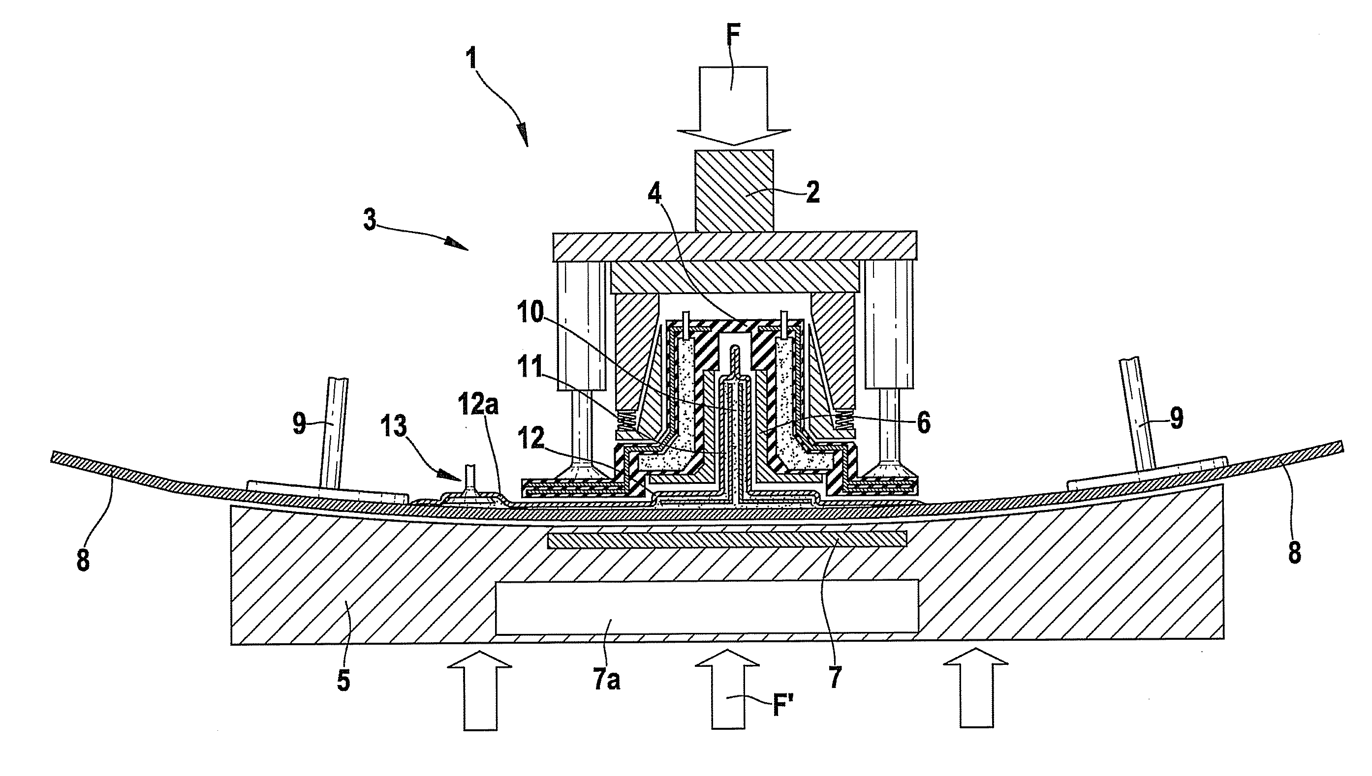
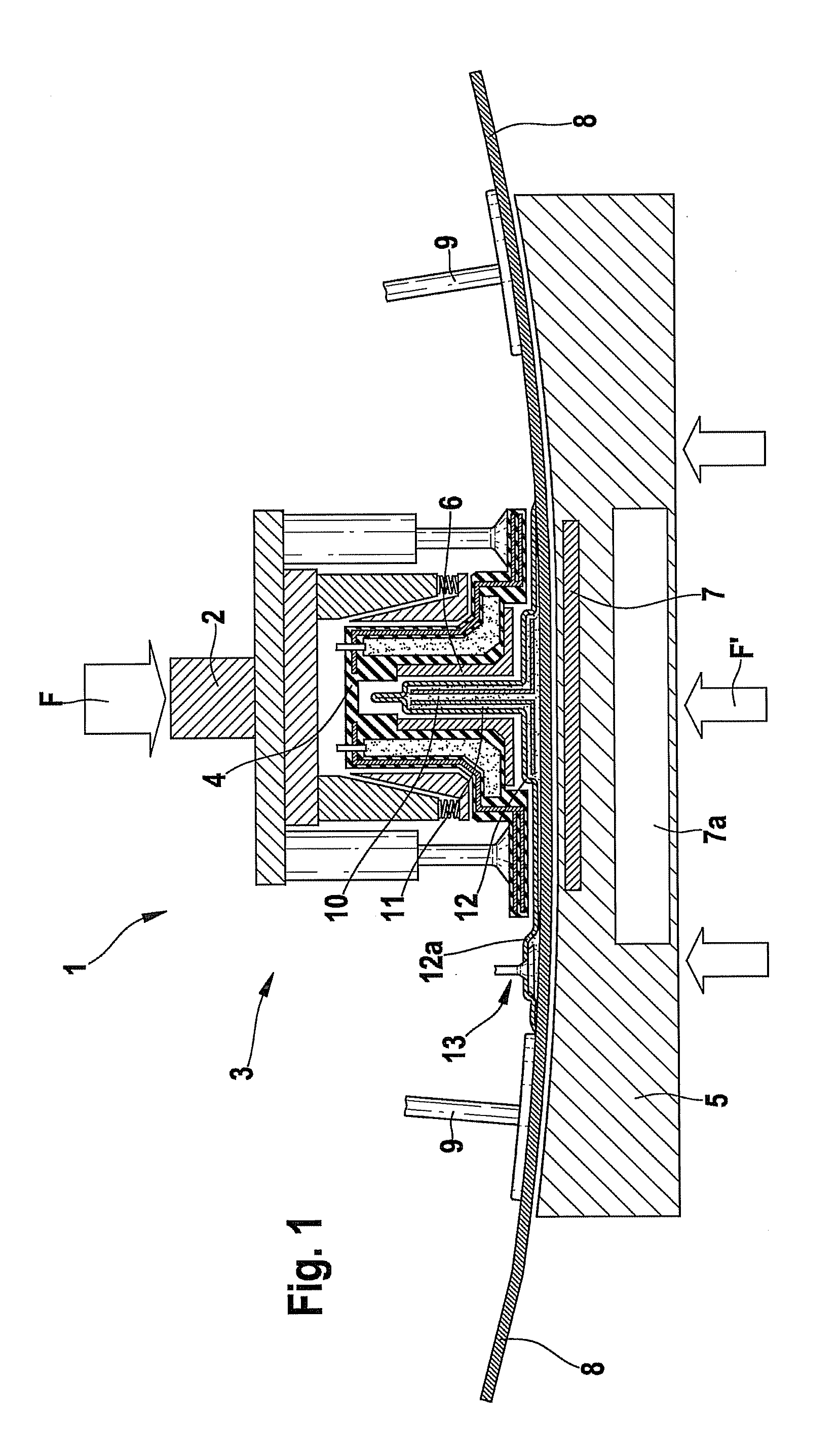
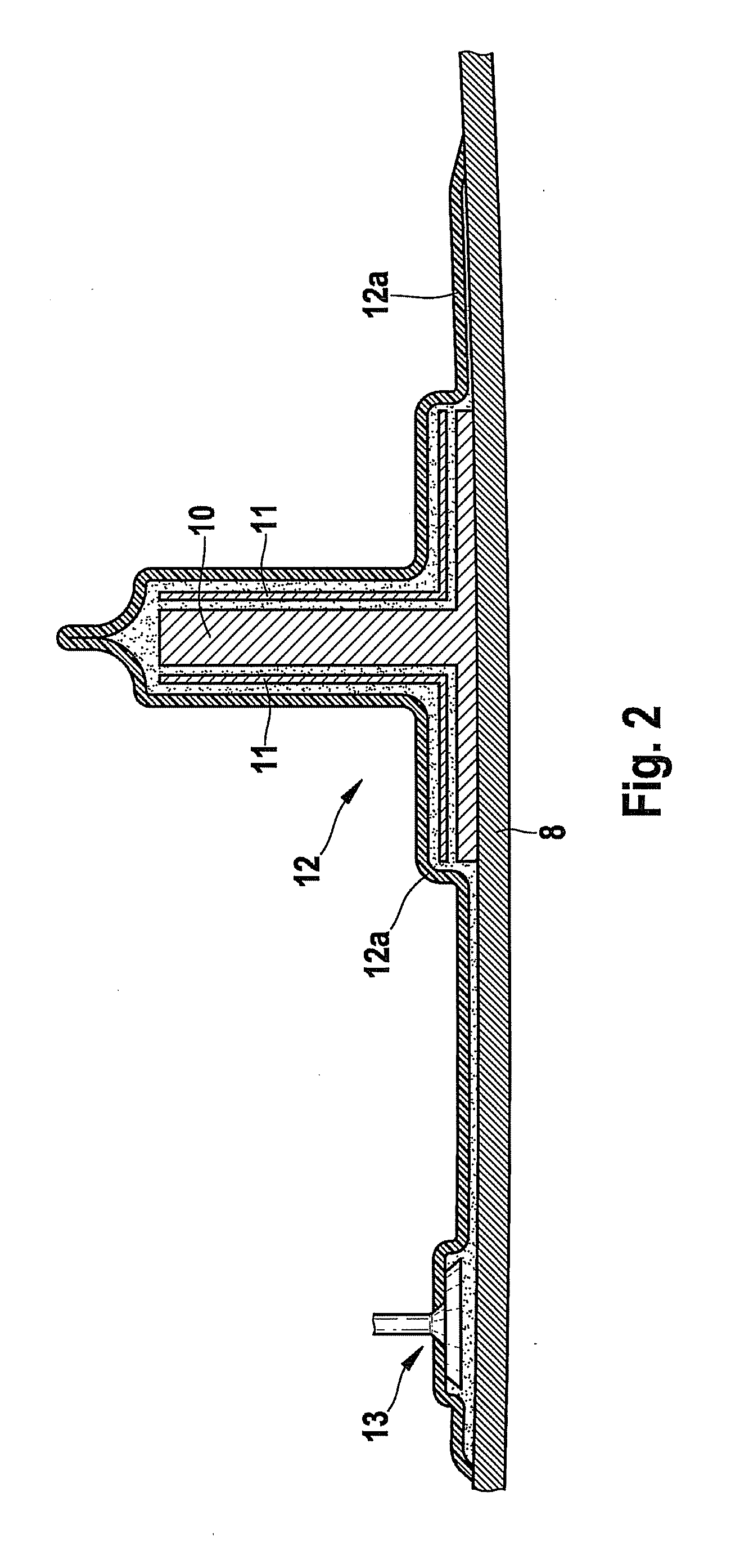
[0042]FIG. 1 is a schematic cross-sectional view of a connecting device 1 according to an embodiment of the invention and FIG. 2 illustrates a schematic, enlarged cross-sectional view of a reinforcement element 10 to be machined.

[0043]The view is a cross-sectional view, but the reinforcement element 10 is to be imagined three-dimensionally standing on the plane of the drawing in its longitudinal direction.

[0044]An already cured fibre composite structure 8, for example a shell component of a fuselage portion of an aircraft, is reinforced with first reinforcement elements 9 and second reinforcements element 10 in a direction perpendicular to the drawing. These reinforcement elements 9, 10 are configured as so-called T-stringers and also already cured, being attached by a foot portion to the fibre composite structure 8, their webs pointing upwards in this case. The fibre composite structure 8 is held in a counter bearing 5, which is arranged in a pressure frame 2 (see FIG. 7).

[0045]The...


PUM

PropertyMeasurementUnit
Temperatureaaaaaaaaaa
Pressureaaaaaaaaaa

Abstract

The invention relates to a method for at least partially reworking or replacing a reinforcement element of a fibre composite structure. In a first method step, at least one fibre layer is arranged on a surface section of the reinforcement element and/or at least one replacement section of the reinforcement element of the same material and same layer structure is arranged on a surface reinforcement section of the fibre composite structure. In a second method step, at least a pressure mat adjusted to the contour of the reinforcement element is disposed above the at least one fibre layer and/or the at least one replacement section of the reinforcement element, wherein the at least one pressure mat is supported and fixed in a nominal position by a fixing frame adjusted to the contour of the reinforcement element. In a third method step, the at least one pressure mat is then acted upon by a pressure medium in order to press the same against the reinforcement element and the fixing frame. In a fourth method step, a hardening of the at least one fibre layer and/or the at least one replacement section of the reinforcement element is carried out. The invention further relates to a corresponding connecting device for carrying out the method.

Description

CROSS-REFERENCE TO RELATED APPLICATIONS[0001]This application is a continuation of PCT / EP2010 / 052251 filed Feb. 23, 2010 and claims the benefit of and priority to U.S. Provisional Application No. 61 / 208,314, filed Feb. 23, 2009 and German patent application No. 10 2009 001 075.0, filed Feb. 23, 2009 the entire disclosures of which are herein incorporated by reference.FIELD OF THE INVENTION[0002]The invention relates to a method for at least partially reworking or replacing a reinforcement element of a fibre composite structure. The invention also relates to an associated connecting device.BACKGROUND OF THE INVENTION[0003]Although they can be applied to any fibre composite structures, the present invention and the problems on which it is based will be described in more detail in relation to a carbon- fibre-reinforced plastics material components (CFRP) of an aircraft structure.[0004]Aircraft components are increasingly being produced, for weight-saving reasons, from fibre composite m...

Claims


Application Information

Patent Timeline
IPC IPC(8): B29C73/10B29C73/30
CPCB29C65/18B29C66/532B29C66/43441B29C66/474B29C66/721B29C66/8161B29C66/8242B29C66/82661B29C66/91231B29C66/91421B29C70/44B29D99/0014B29K2105/06B29K2307/00B29L2031/3076B29C66/81455B29C66/91212B29C66/961B29C65/30B29C66/8322B29C66/1122B29C66/61B29C66/73751
Inventor MARQUARDT, HANS
Owner AIRBUS OPERATIONS GMBH
Why Eureka
Try Eureka