Connection structure and a connection method for connecting a differential signal transmission cable to a circuit board

a technology connection structure, which is applied in the direction of coupling device connection, final product manufacturing, sustainable manufacturing/processing, etc., can solve the problems of deterioration in the characteristics and achieve the effect of improving the mounting density of differential signal transmission cable(s)

Active Publication Date: 2012-03-15
HITACHI METALS LTD
View PDF5 Cites 20 Cited by
  • Summary
  • Abstract
  • Description
  • Claims
  • Application Information

AI Technical Summary

Benefits of technology

[0043]According to the invention, it is possible to provide a connection method and a connection structure for connecting a differential signal transmission cable to a circuit board, by which the fusion or deformation of the insulator during the solder-connecting process can be prevented, and the mounting density of the differential signal transmission cable(s) can be improved.

Problems solved by technology

), thereby likely causing the deterioration in characteristics of the differential signal transmission cable 201.

Method used


Image

  • Connection structure and a connection method for connecting a differential signal transmission cable to a circuit board
  • Connection structure and a connection method for connecting a differential signal transmission cable to a circuit board
  • Connection structure and a connection method for connecting a differential signal transmission cable to a circuit board

Examples


first preferred embodiment

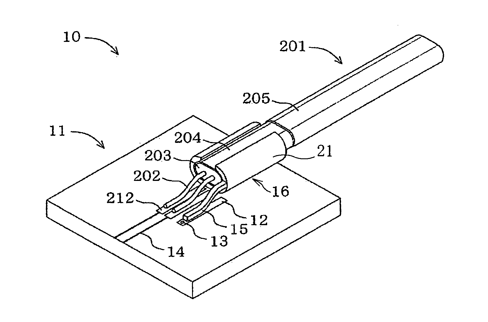
[0069]FIG. 1 is a perspective view showing a connection structure for connecting a differential signal transmission cable to a circuit board in the first preferred embodiment according to the present invention.

[0070](Connection Structure 10)

[0071]FIG. 1 shows a connection structure 10 for connecting a differential signal transmission cable 201 to a circuit board 11 in the first preferred embodiment. According to the connection structure 10, the differential signal transmission cable 201, in which an outer conductor 204 is provided around a circumference of a pair of signal line conductors 202 via an insulator 203 and the pair of signal line conductors 202 are exposed to the outside from a tip of the differential signal transmission cable 201, is solder-connected to the circuit board 11.

[0072]In addition, the differential signal transmission cable 201 has the same configuration as the differential signal transmission cable described referring to FIG. 20, also, the circuit board 11 ha...

second preferred embodiment

[0102]Next, a connection structure for connecting a differential signal transmission cable to a circuit board in the second preferred embodiment according to the present invention will be explained below.

[0103](Connection Structure 100)

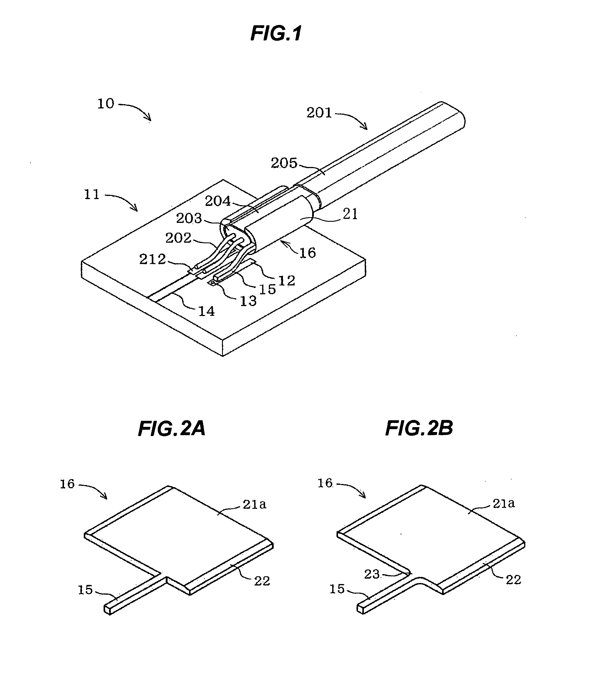
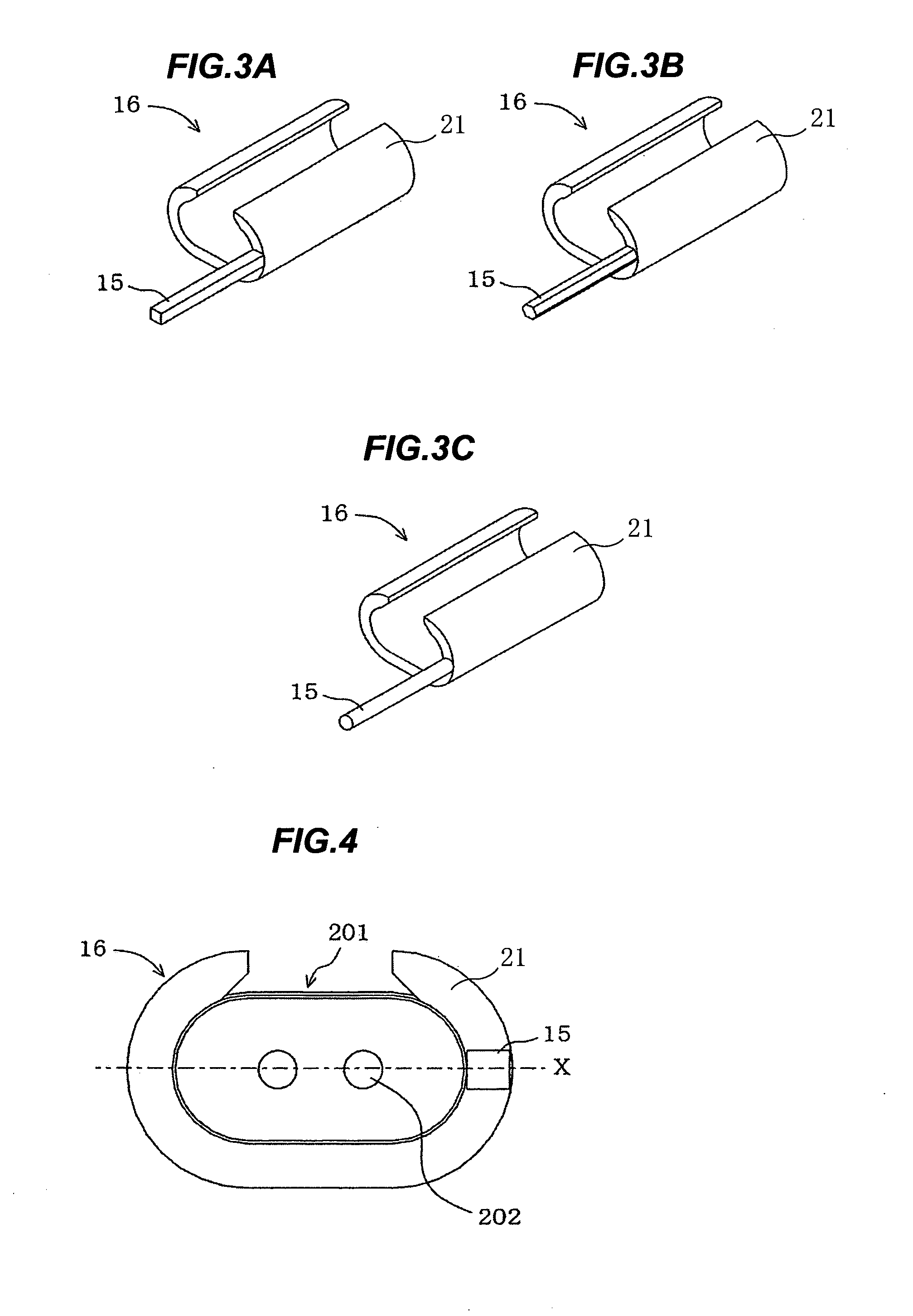
[0104]FIG. 10 shows a connection structure 100 in the second preferred embodiment, which is similar to the connection structure 10 in the first preferred embodiment, except a shield-connecting terminal 101 comprising two solder-connecting pins 15 which sandwich the pair of signal line conductors 202, and a circuit board 102 including two grand pads 12 which are formed in correspondence with the two solder-connecting pins 15.

[0105]Referring to FIG. 10 and FIG. 11A, the shield-connecting terminal 101 comprises a main body 21 formed of a metallic plate 21a and a pair of solder-connecting pins 15. The main body 21 and the solder-connecting pins 15 are formed integrally (i.e. in one-piece). The main body 21 is bent to surround the circumference of the oute...


PUM

PropertyMeasurementUnit
circumferenceaaaaaaaaaa
shapeaaaaaaaaaa
circular shapeaaaaaaaaaa

Abstract

A connection structure for connecting a differential signal transmission cable to a circuit board. A differential signal transmission cable includes an outer conductor provided around a pair of signal line conductors via an insulator. Parts of the signal line conductors are exposed from a tip of the differential signal transmission cable. A circuit board is provided with a pair of signal pads and a ground pad. A shield-connecting terminal includes a main body which is crimp-connected to the outer conductor and a solder-connecting pin which is solder-connected to the ground pad. The exposed parts of the signal line conductors are solder-connected to the signal pads, respectively, and the outer conductor is solder-connected to the ground pad via the solder-connecting pin of the shield-connecting terminal.

Description

[0001]The present application is based on Japanese patent application No. 2010-248452 filed on Nov. 5, 2011, the entire contents of which are incorporated herein by reference.BACKGROUND OF THE INVENTION[0002]1. Field of the Invention[0003]The present invention relates to a connection structure and a connection method for connecting a differential signal transmission cable to a circuit board.[0004]2. Description of the Related Art[0005]In servers, routers, and other storage devices for high speed digital signal transmission at several Gbit / s or more, a differential signal transmission has been used for a signal transmission between equipments or between substrates (circuit boards) in an equipment.[0006]The differential signal transmission (differential signaling) is to transmit two 180° phase-inverted signals through respective ones of a pair of signal line conductors, and to synthesize and output a difference between the two 180° phase-inverted signals received at a receiver side. S...

Claims


Application Information

Patent Timeline
Patent Type & Authority Applications(United States)
IPC IPC(8): H01R4/18H05K3/00
CPCH01R9/035H05K1/111H01R13/6592H05K3/3405Y10T29/49149H01R4/023H01R12/62H01R43/0256H05K2201/10356H01R13/65915Y02P70/50
Inventor NONEN, HIDEKISUGIYAMA, TAKAHIROKUMAKURA, TAKASHI
Owner HITACHI METALS LTD
Why Eureka
Try Eureka