Cooling structure for rotating electric machine

Inactive Publication Date: 2012-03-15
AISIN AW CO LTD
View PDF0 Cites 16 Cited by
  • Summary
  • Abstract
  • Description
  • Claims
  • Application Information

AI Technical Summary

Benefits of technology

[0024]According to the seventh aspect, the support projecting portion for supporting the bearing of the rotor shaft can be utilized to con

Problems solved by technology

The amount of coolant supplied is therefore not necessarily the amount of coolant falling by the force of gravity to the coil end portion, thus resulting in reduced cooling efficiency.
However

Method used


Image

  • Cooling structure for rotating electric machine
  • Cooling structure for rotating electric machine
  • Cooling structure for rotating electric machine

Examples


Example

1. First Embodiment

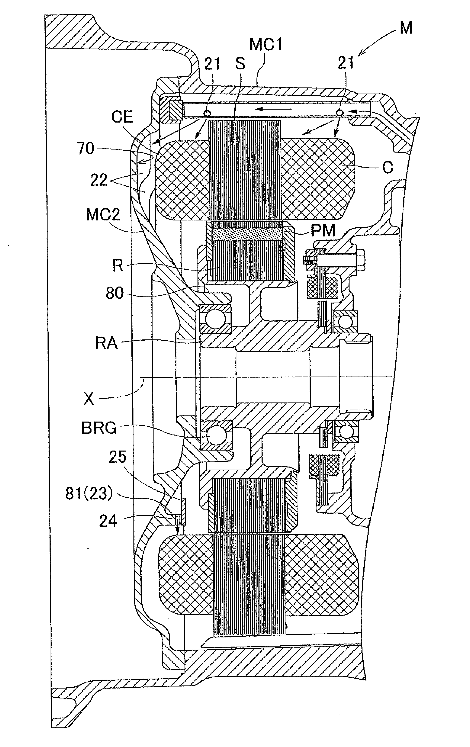
[0034]FIG. 1 shows a cross-sectional view of a rotating electric machine M to which the cooling structure according to the present embodiment is applied. As shown in FIG. 1, the rotating electric machine M is constituted such that a stator S and a rotor R are accommodated inside a space that is formed by a case body MC1 and a cover MC2 that covers an opening portion of the case body MC1. The stator S is fixed to the case body MC1.

[0035]The rotating electric machine M may output the driving force (rotary force) generated by the rotating electric machine M to outside the rotating electric machine M. In such case, the rotating electric machine M functions as an electric motor. By transmitting a driving force (rotary force) to the rotating electric machine M from outside, the rotating electric machine M may also function as a generator that generates power. The present embodiment will be described using an example in which the rotating electric machine M functions as ...

Example

2. Second Embodiment

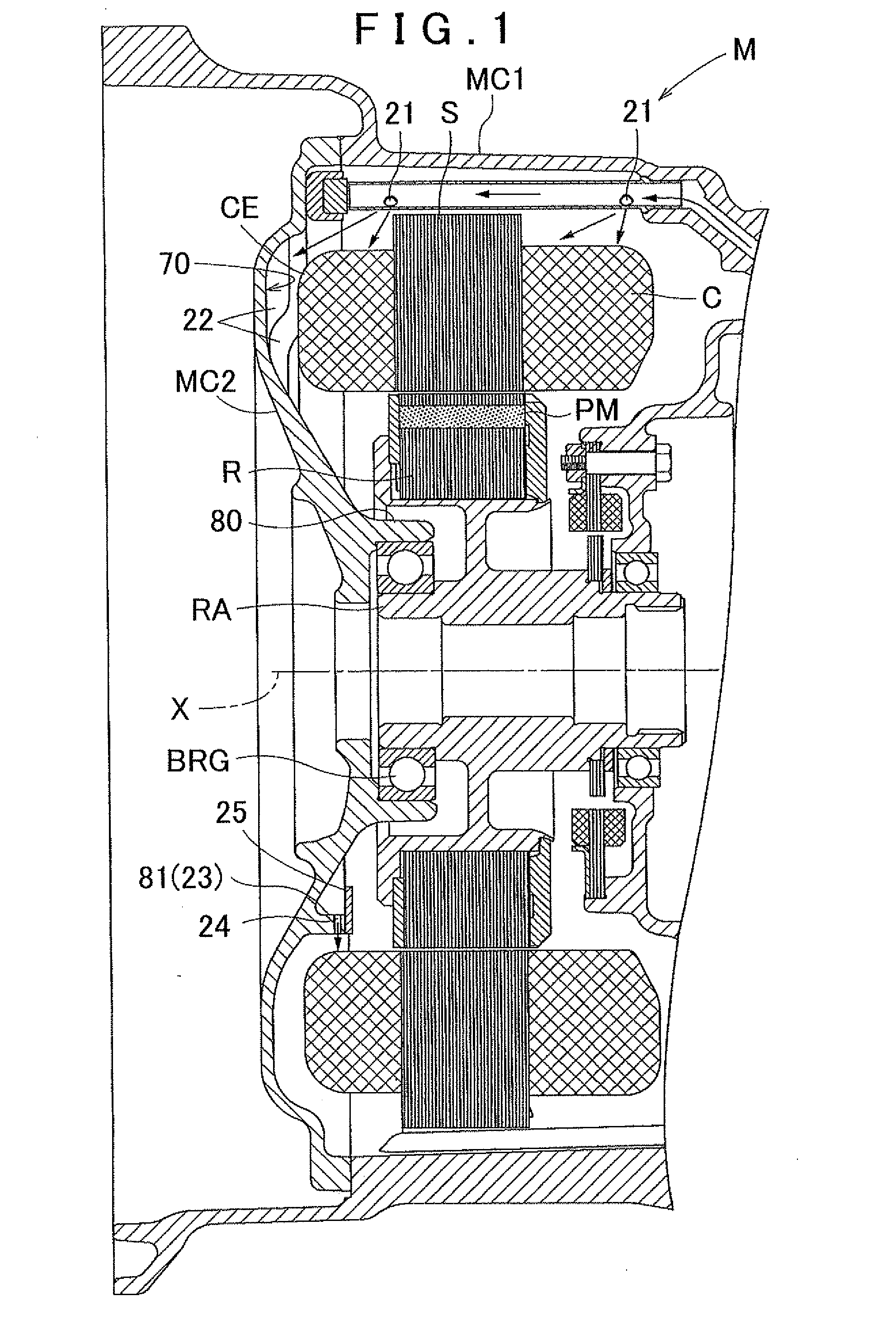
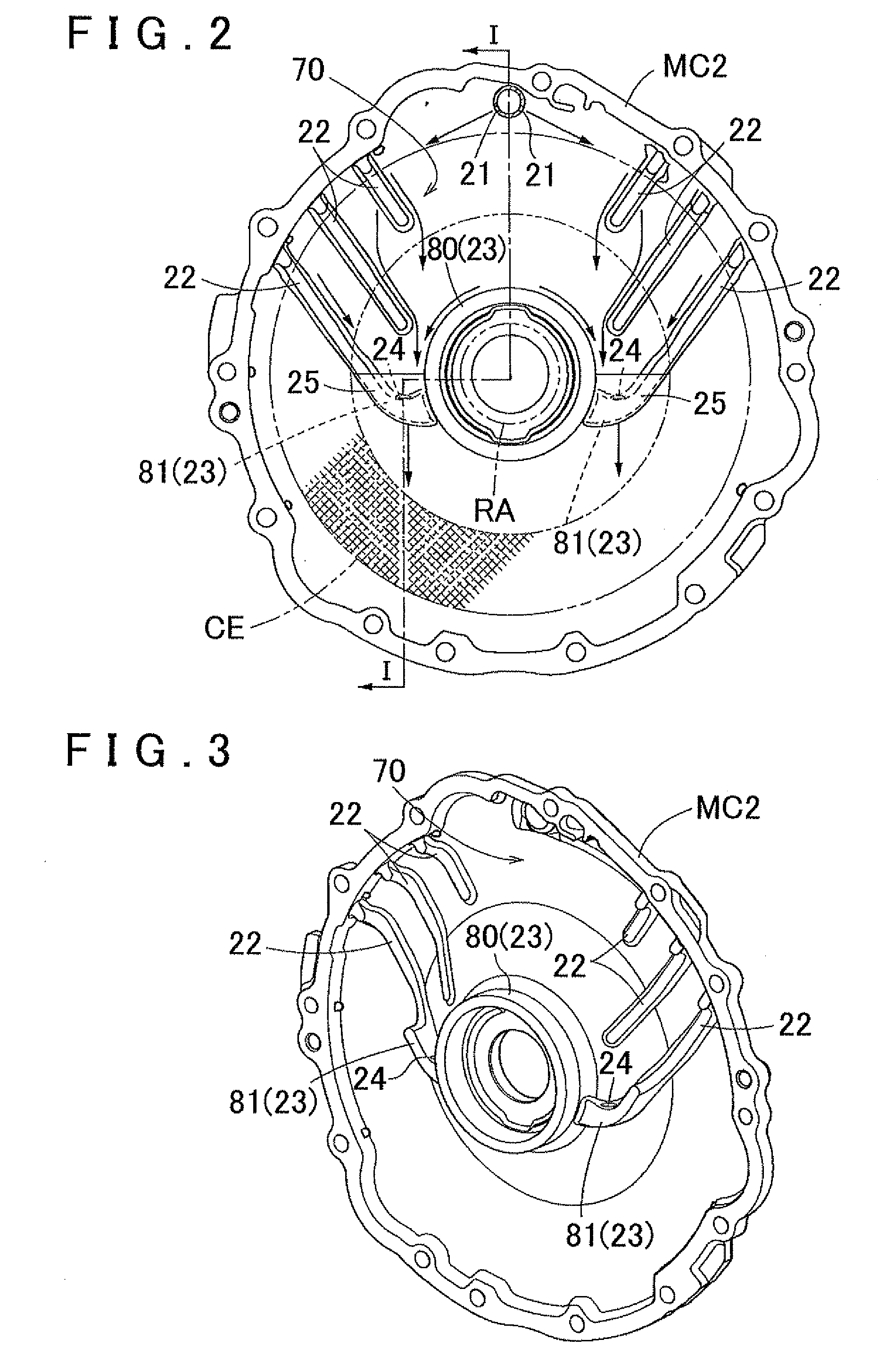
[0053]A second embodiment of the present invention will be explained next. In the above description of the first embodiment, the collection projecting portion 81 is configured so as to extend upward and radially outward from the outer circumferential surface of the support projecting portion 80. However, the collection portion 23 according to the present embodiment differs from the first embodiment in that the collection portion 23 is configured as separate from the support projecting portion 80. Also, in the above description of the first embodiment, part of the plurality of protrusion portions 22 is provided as connected to the collection projecting portion 81. However, the protrusion portion 22 according to the present embodiment differs from the first embodiment in that the protrusion portions 22 are all provided as separate from the collection projecting portion 23. The following description will focus on points where the protrusion portion 22 and the collec...


PUM


Abstract

A cooling structure for a rotating electric machine, having a coolant supply portion, and configured to supply a coolant to a coil end portion of a stator. A protrusion portion is provided on a portion of a coil end facing area, and projects toward the coil end portion side and extends downward and toward a radially inner side of the coil end portion, wherein the coil end facing area is a section that faces the coil end portion on an inner wall surface of a case that accommodates the stator. A collection portion collects the coolant distributed along the protrusion portion. A drip portion is disposed on the radially inner side of the coil end portion at a position that axially overlaps with the coil end portion as viewed from the radial direction, wherein the coolant collected in the collection portion drips from the drip portion.

Description

INCORPORATION BY REFERENCE[0001]The disclosure of Japanese Patent Application No. 2010-205391 filed on Sep. 14, 2010 including the specification, drawings and abstract is incorporated herein by reference in its entirety.BACKGROUND OF THE INVENTION[0002]The present invention relates to a cooling structure for a rotating electric machine in which a stator includes a coil.[0003]1. Description of the Related Art[0004]A rotating electric machine used in the past includes a stator having coils, and a rotor having permanent magnets. In this type of rotating electric machine, the coils and the permanent magnets generate a large amount of heat depending on the output. If the heat generated by the coils becomes excessive, there may be an insulation breakdown of insulating varnish that insulates conductors forming the coils from each other, and insulating paper that insulates coils of each phase from each other. Therefore, cooling of the coils is desired. Technology for this purpose includes a...

Claims


Application Information

Patent Timeline
IPC IPC(8): H02K9/19
CPCH02K9/19H02K5/20H02K5/203
Inventor MURAKAMI, SATOSHINAKAMORI, YUKINORI
Owner AISIN AW CO LTD
Why Eureka
Try Eureka