Rotor for Motor

a rotor and motor technology, applied in the direction of machines/engines, mechanical equipment, liquid fuel engines, etc., can solve the problems of affecting the operation of the motor, prone to fatigue, more noise, etc., and achieve the effect of reducing the axial vibration of the hub

Inactive Publication Date: 2012-03-15
SUNONWEALTH ELECTRIC MACHINE IND
View PDF4 Cites 2 Cited by
  • Summary
  • Abstract
  • Description
  • Claims
  • Application Information

AI Technical Summary

Benefits of technology

[0013]An objective of the present invention is to provide a rotor for a motor that provides buffering effect between a hub and a shaft to reduce axial vibration of the hub relative to the shaft.
[0014]Another objective of the present invention is to provide a rotor for a motor that prevents leaking of the lubricating oil received in the bearings of the motor.

Problems solved by technology

Furthermore, the metal C-clip 73 continuously impinges on a top face of the hub 71 and generates noise, adversely affecting the operation of the motor 8.
Thus, the hub 91 moves axially relatively to the shaft 92 when the rotor 9 rotates, resulting in noise.
Furthermore, the retainer 93 is made of rigid material such as metal and thus liable to fatigue after a period of time.
The axial gap between each resilient retaining plate 932 and the end wall of the engaging groove 921 becomes larger, causing more noise and adversely affecting the operation of the motor 8.
As a result, the lubricating oil in the bearings 94 of the motor 9 is liable to leak via the slits 933, shortening the service life of the motor 8.

Method used


Image

  • Rotor for Motor
  • Rotor for Motor
  • Rotor for Motor

Examples


Embodiment Construction

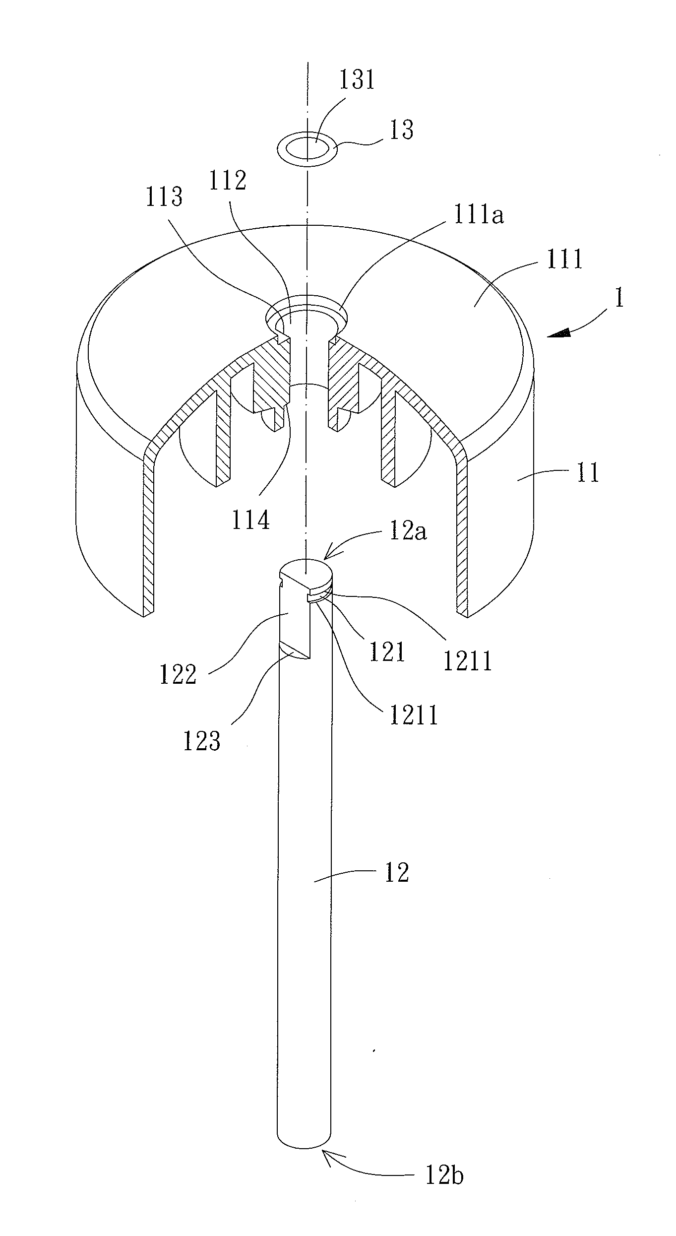
[0030]With reference to FIGS. 5 and 6, a rotor 1 for a motor of an embodiment according to the preferred teachings of the present invention includes a hub 11, a shaft 12, and an engaging member 13. The shaft 12 is fixed to the hub 11 through the engaging member 13.

[0031]The hub 11 includes a top face 111 having a through-hole 112 extending through the hub 11. The through-hole 112 can be located in a center of the top face 111. An inner periphery of the through-hole 112 includes a planar face 113 and a first stop face 114. The planar face 113 extends parallel to an axis of the through-hole 112. The first stop face 114 extends perpendicularly to the axis of the through-hole 112. However, the shapes of the planar face 113 and the first stop face 114 are not limited to those shown in FIGS. 5 and 6.

[0032]The shaft 12 includes a first end 12a and a second end 12b. An outer periphery of the shaft 12 adjacent to the first end 12a includes a reduced section 121, a chamfered face 122, and a s...


PUM


Abstract

A rotor for a motor includes a hub having a through-hole. A shaft extends through the through-hole and includes an outer periphery having a reduced section, wherein the reduced section has two end walls in an axial direction of the motor. The engaging member includes a hole through which the shaft extends. The engaging member is tightly engaged with the reduced section while tightly pressing against the two end walls of the reduced section. The engaging member is a resilient, continuous annular member free of grooves and notches. When the rotor is mounted in a motor, axial vibration of the hub relative to the shaft is reduced, and leakage of lubricating oil in the bearings of the motor is prevented.

Description

BACKGROUND OF THE INVENTION[0001]1. Field of the Invention[0002]The present invention relates to a rotor for a motor and, more particularly, to a rotor that can reduce axial vibration of a hub relative to a shaft and that can avoid leaking of lubricating oil received in the bearings of a motor.[0003]2. Description of the Related Art[0004]With reference to FIG. 1, a conventional rotor 7 for a motor includes a hub 71, a shaft 72, and a metal C-clip 73. The hub 71 includes a through-hole 711. An inner periphery of the through-hole 711 has a planar face 712 and a first stop face 713. The shaft 72 includes an outer periphery having an annular engaging groove 721, a chamfered face 722, and a second stop face 723. The metal C-clip 73 has an opening 731 in a side thereof.[0005]With reference to FIGS. 1 and 2, in assembly of the rotor 7, the shaft 72 is extended through the through-hole 711 with the chamfered face 722 abutting the planar face 712, allowing joint rotation of the hub 71 and th...

Claims


Application Information

Patent Timeline
Patent Type & Authority Applications(United States)
IPC IPC(8): H02K7/14
CPCF04D29/263H02K5/24F04D25/0606H02K7/14H02K7/003
Inventor HORNG, ALEXSHAN, DUO-NIANWU, ZHE-HAO
Owner SUNONWEALTH ELECTRIC MACHINE IND
Why Eureka
Try Eureka