Brushless motor control device and brushless motor system

a control device and motor technology, applied in the direction of motor/generator/converter stopper, electronic commutator, dynamo-electric converter control, etc., can solve the problem of inability to secure sufficient responsiveness, inability to set the control response frequency for securing sufficient responsiveness originally impossible, and inability to achieve the effect of preventing the impossibility of intended control

Inactive Publication Date: 2012-03-15
HITACHI CAR ENG CO LTD
View PDF16 Cites 17 Cited by
  • Summary
  • Abstract
  • Description
  • Claims
  • Application Information

AI Technical Summary

Benefits of technology

[0022]The present invention makes it possible to prevent the impossibility of the intended control resulting ...

Problems solved by technology

Further, with the diversification of the purposes of use, the load on a brushless motor changes in various ways, and thus the sensorless control has to be implemented even in situations with a high load variation and an excessive load.
Thus, even if the control response frequency is set high so as to realize high trackability to sharp changes in the load on the motor, it is impossible to secure sufficient responsiveness in cases where the actual change in the load is even faster.
Meanwhile, there are also cases where the setting of the control response frequency for securing sufficient responsiveness is originally impossi...

Method used


Image

  • Brushless motor control device and brushless motor system
  • Brushless motor control device and brushless motor system
  • Brushless motor control device and brushless motor system

Examples


Embodiment Construction

[0028]In the following, the configuration and operation of a brushless motor control device in accordance with an embodiment of the present invention will be described with reference to FIGS. 1-5.

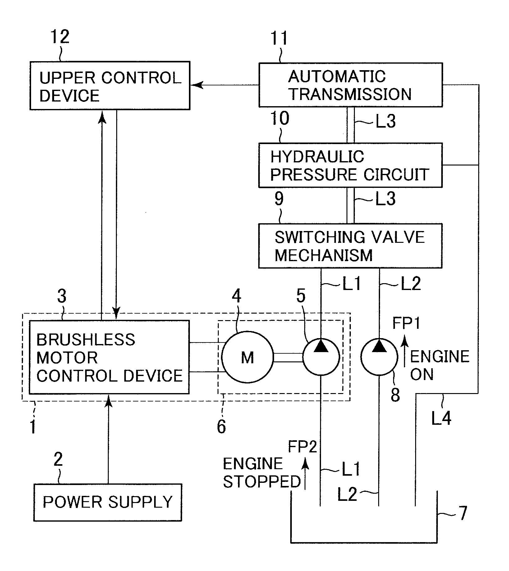
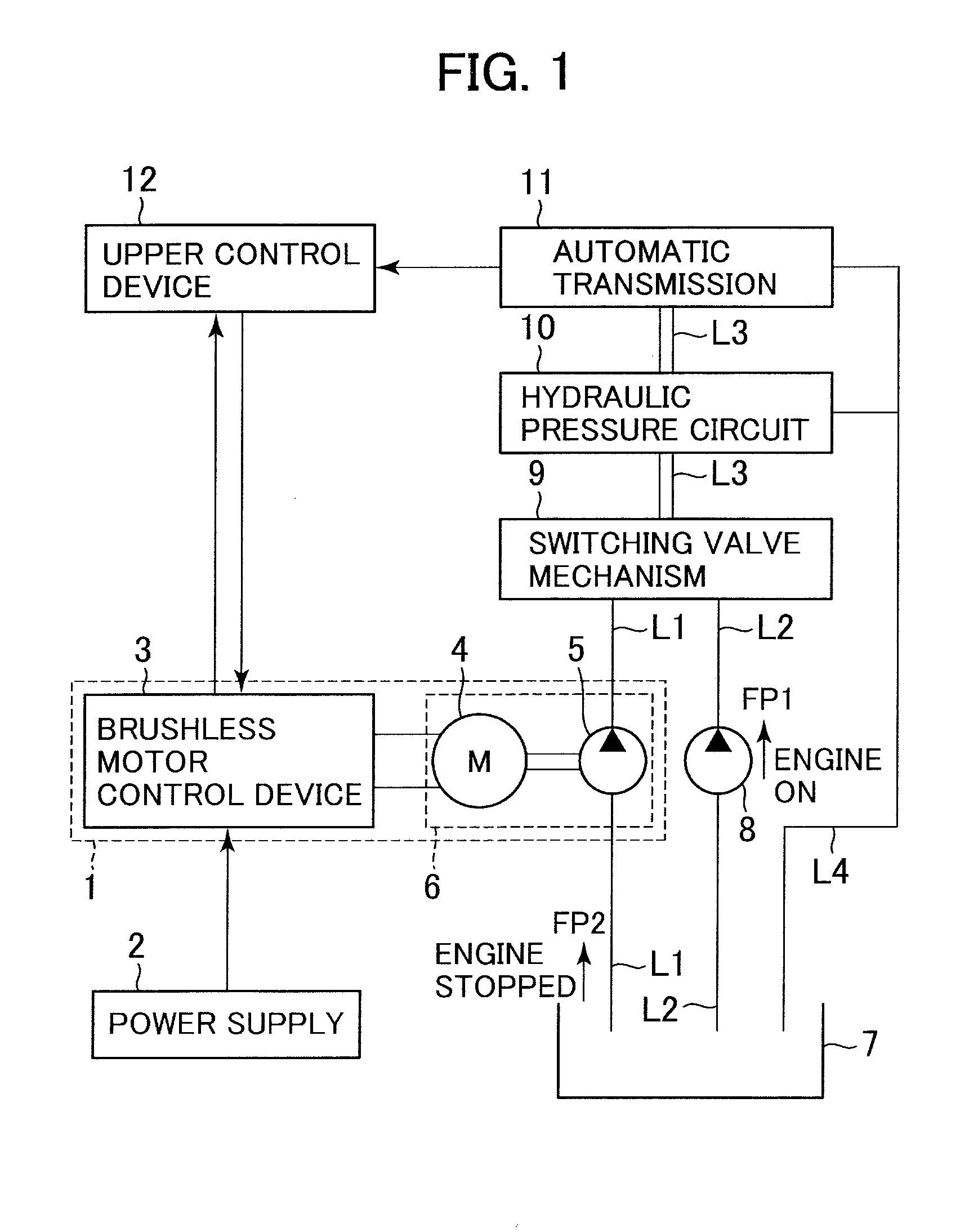
[0029]First, the overall configuration of an electric oil pump system employing the brushless motor control device in accordance with this embodiment will be explained referring to FIG. 1.

[0030]FIG. 1 is a block diagram showing the overall configuration of the electric oil pump system employing the brushless motor control device in accordance with an embodiment of the present invention.

[0031]The electric oil pump system 1 comprises a brushless motor control device 3 and an electric oil pump unit 6. The electric oil pump unit 6 includes a brushless motor 4 and an electric oil pump 5. The brushless motor control device 3 controls the rotation of the brushless motor 4. The electric oil pump 5 is driven by driving force from the output shaft of the brushless motor 4. The electric oil pump syste...


PUM


Abstract

Provided are a brushless motor control device and a brushless motor system capable of preventing impossibility of intended control of a brushless motor resulting from false recognition that the brushless motor is in operation in spite of stoppage of the brushless motor. A brushless motor control unit calculates a voltage instruction, representing voltages to be applied to the brushless motor, according to a control instruction supplied from an upper control device. A position error calculation unit calculates and estimates a position error between d-q-axes and dc-qc-axes as rotational coordinate axes by use of the voltage instruction outputted by the brushless motor control unit, current values acquired by a coordinate transformation unit and revolution speed for control of the brushless motor. A fault detection unit judges whether the brushless motor is faulty or not based on the position error calculated by the position error calculation unit.

Description

BACKGROUND OF THE INVENTION[0001]1. Field of the Invention[0002]The present invention relates to a brushless motor control device and a brushless motor system. The invention more specifically relates to a brushless motor control device and a brushless motor system suitable for sensorless control not using a sensor for detecting the rotor position of a brushless motor.[0003]2. Description of the Related Art[0004]Hybrid vehicles (driven by a gasoline engine and an electric motor) and idling stop vehicles (stopping the engine when the vehicle stops) are well known to be effective for improving the mileage (fuel efficiency) and alleviating environmental problems. Such a vehicle is equipped with a mechanical oil pump (driven by the driving force of the engine) and an electric oil pump (driven by electric power supplied from outside (e.g., battery)) in order to supply necessary hydraulic pressure to the transmission mechanism and the hydraulic pressure controller of the automatic transmis...

Claims


Application Information

Patent Timeline
IPC IPC(8): H02H7/08H02P6/18H02P6/06H02P6/08H02P6/182H02P6/28
CPCH02P29/021H02P21/146H02P21/18H02P29/0241G05B23/0235H02P2203/05H02P6/28H02P6/18
Inventor OTA, HIROYUKINOJIRI, YUUKOUSUZUKI, IPPEINODA, JUNICHI
Owner HITACHI CAR ENG CO LTD
Why Eureka
Try Eureka