
Parking support device

a technology for supporting devices and parking spaces, applied in the direction of instruments, transportation and packaging, using reradiation, etc., can solve the problems of increasing length, increasing the accuracy of measuring parking spaces, and unable to approximate the real corner with a high degree of precision, and achieve the effect of high degree of precision

Active Publication Date: 2012-03-15
MITSUBISHI ELECTRIC CORP
View PDF3 Cites 29 Cited by
  • Summary
  • Abstract
  • Description
  • Claims
  • Application Information

AI Technical Summary

Benefits of technology

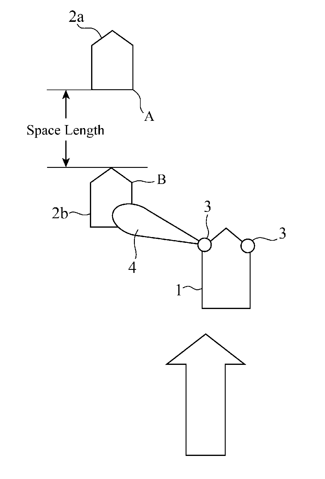
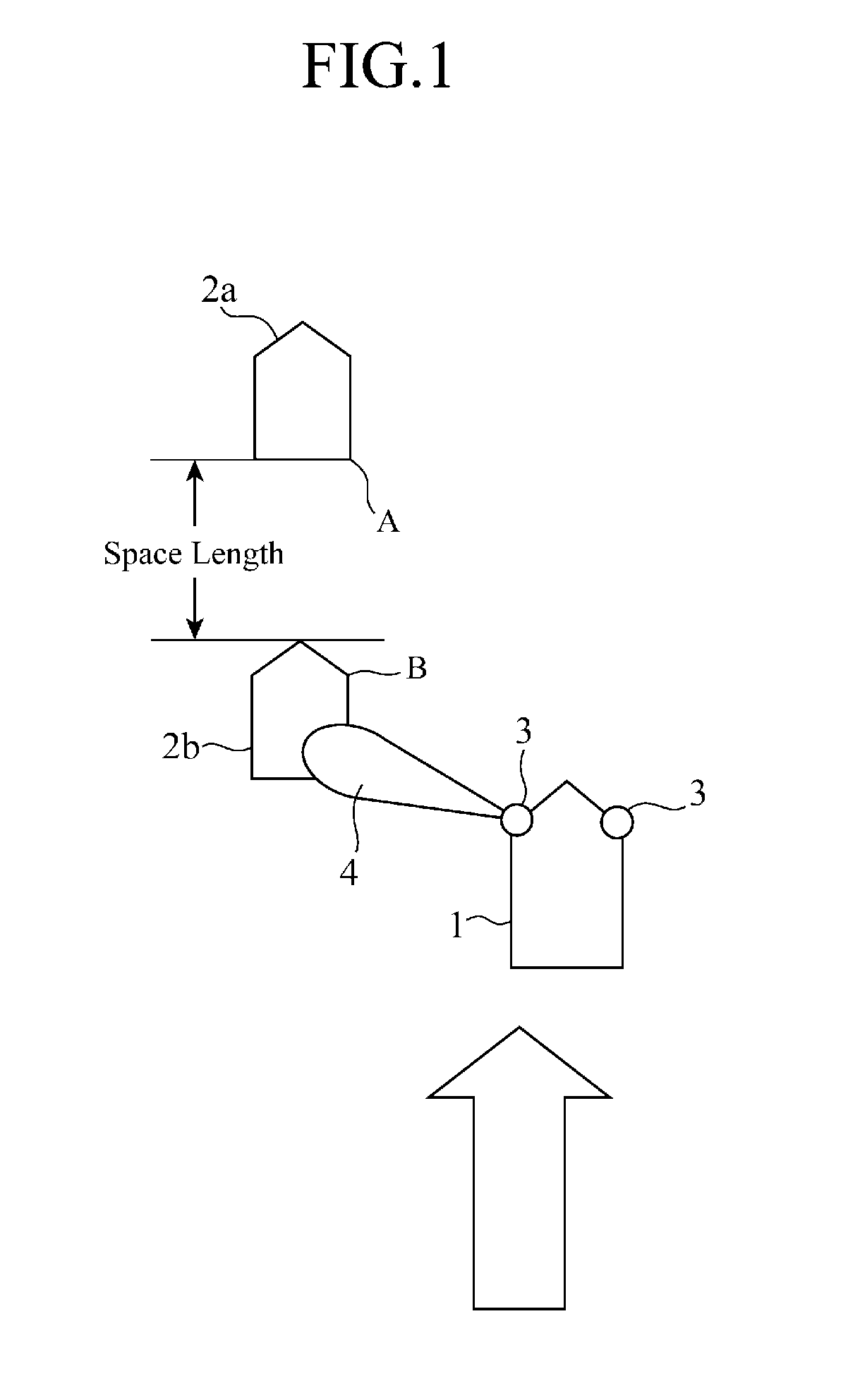
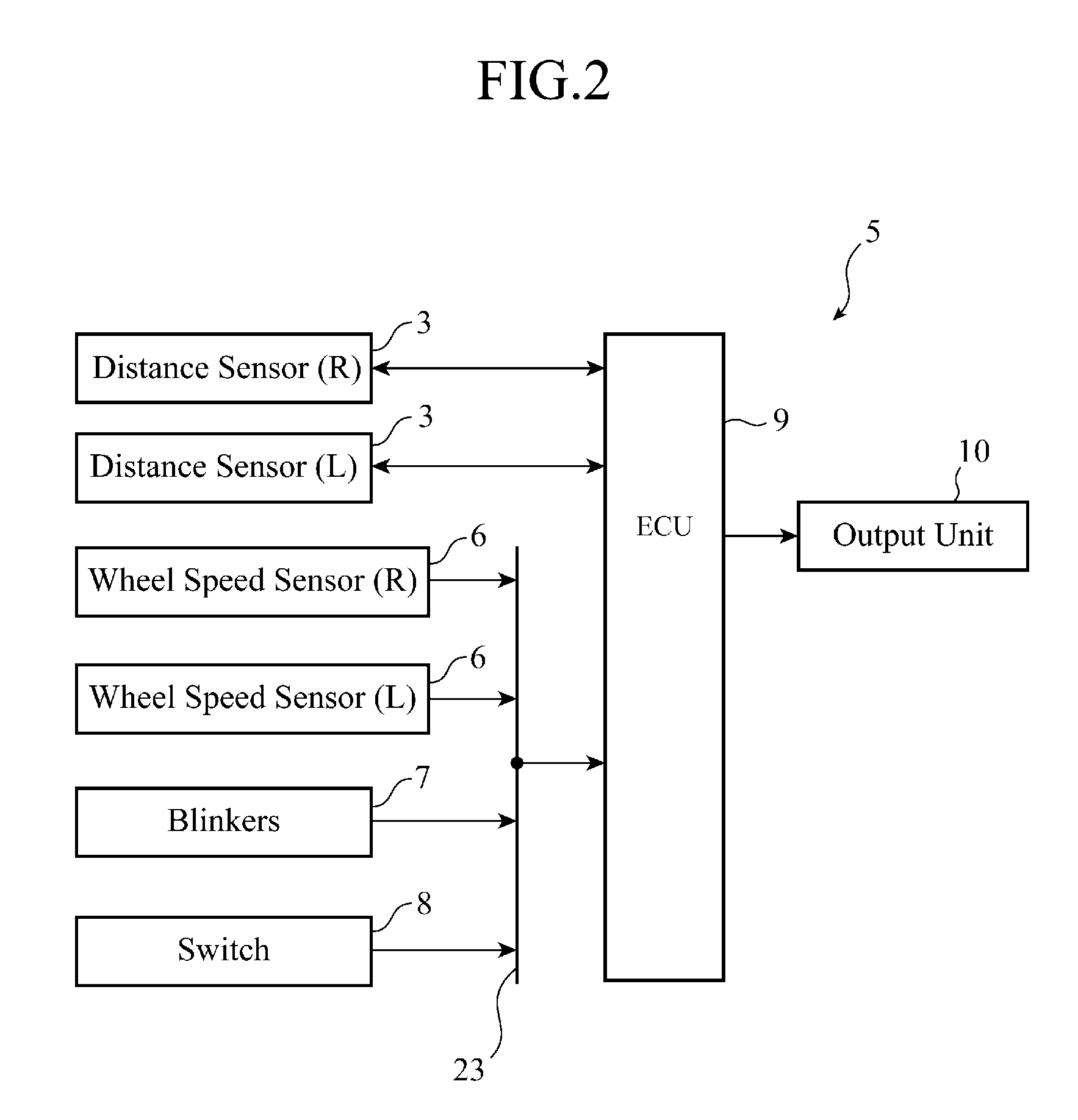
[0011]The parking support device according to the present invention extracts detection point data corresponding to a corner portion of an object to be detected from detection point data showing a series of detection points at each of which the distance to the object to be detected is detected by the distance sensor unit, performs a noise component removing process and a data complementing process using a curve approximation of the series of detection points on the extracted detection point data, estimates reflection points of a detection wave in the corner portion on the basis of the acquired detection point data and sensor position data showing the moving path of the distance sensor moving as the vehicle travels, and measures the length of a parking space adjacent to the object to be detected on the basis of the position of the corner which is determined from the positions of the estimated reflection points to determine if the vehicle can be parked in the parking space. The parking support device has an advantage of being able to measure the parking space for the vehicle with a high degree of precision by doing in this way.

Problems solved by technology

However, while the approximate expression is changed according to the length of the obstacle in this method, it becomes impossible for the approximated curve to approximate the real corner with a high degree of precision as a straight line portion of the obstacle which consists of a linearly-created sequence of points of the reflection data increases in length.
More specifically, there is a tendency for the measurement accuracy of the parking space to get worse.
Also in the case of using the method described in patent reference 2, it becomes impossible for the approximated curve to approximate the real corner with a high degree of precision as a straight line portion of the obstacle increases in length, and there is a tendency for the measurement accuracy of the parking space to get worse.

Method used


Image

  • Parking support device
  • Parking support device
  • Parking support device

Examples


embodiment 2

[0117]The parking support device according to above-mentioned Embodiment 1 cannot determine the position of a corner of an object to be detected strictly when the corner portion of the object to be detected has a curved shape.

[0118]FIG. 14 is a view for explaining a factor that disables the parking support device to determine the position of such a corner strictly. In FIG. 14, a distance sensor 3 applies a detection wave (shown by a dash-dotted arrow) of an ultrasonic wave to an object to be detected 2a, receives a reflected wave (shown by a solid arrow) from a reflection point 18 on the object to be detected 2a, and detects the distance to the object to be detected 2a while moving along the traveling path 20 of a vehicle 1.

[0119]When the object to be detected 2a has a corner portion having a curvature, there may be a case in which no reflected wave is received by the distance sensor 3 and the position of a corner end point 19 cannot be determined even though the corner curvature is...


PUM


Abstract

A parking support device is provided for extracting detection point data corresponding to a corner portion of a parked vehicle 2 from detection point data showing a series of detection points at each of which the distance to the parked vehicle 2 is detected, performing a noise component removing process and a data complementing process using a curve approximation of the series of detection points on the extracted detection point data, estimating reflection points of a detection wave in the corner portion from the detection point data and sensor position data showing a moving path of a distance sensor 3, and measuring the length of a parking space adjacent to the parked vehicle 2 according to a corner position which is determined from the positions of the estimated reflection points to determine if a vehicle 1 can be parked in the parking space.

Description

FIELD OF THE INVENTION[0001]The present invention relates to a parking support device which measures a parking space for parallel parking, and notifies a driver if the driver can park his or her vehicle in the parking space.BACKGROUND OF THE INVENTION[0002]A conventional device applies a detection wave and collects reflection data from an object to be detected, performs parabolic approximation or elliptic approximation on the sequence of points of the reflection data, and performs a rotation correction process on this approximated data to calculate the position of a corner of an obstacle such as a parked vehicle (for example, refer to patent reference 1). Rotation correction means a method of correcting the reflection position of the detection wave in such a way that the angle which a straight line connecting between the position of a sonar for applying the detection wave and the reflection position forms with the moving path of the sonar decreases with increase in the ratio of the ...

Claims


Application Information

Patent Timeline
Patent Type & Authority Applications(United States)
IPC IPC(8): G08G1/14G01S13/931G01S15/931
CPCG01S2015/935G01S13/931B62D15/027G01S15/931G01S2013/9314G01S2015/937G01S2013/9323G01S2013/93274G01S2013/9324
Inventor INOUE, SATORUSUZUKI, RYOTAROAKAZA, MITSUAKI
Owner MITSUBISHI ELECTRIC CORP
Learn More